29
SECTION J - TROUBLESHOOTING THE ATC MODULATOR
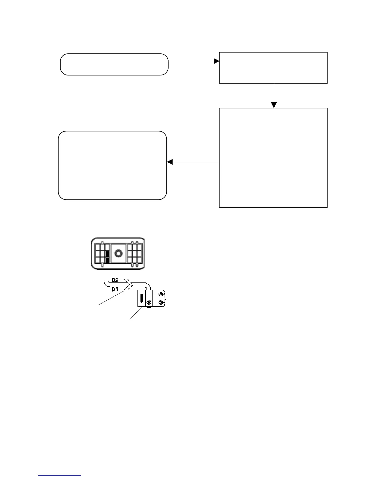
Verify 10.0 to 12.0 OHMS across the
ATC modulator leads. Verify no
continuity from ATC modulator
connector pins to ground. Verify +12
VDC is not measured at any ATC
modulator connector pins. Check for
corroded or damaged ATC modulator
wiring and connectors. If a circuit fault
is found, isolate the area needing
repair by repeating the measurements
at all connections in the ATC modulator
circuit.
Make repairs to wiring or replace ATC
modulator. Reconnect all connectors
to the EC-30
™
controller and ATC
modulator. Reset fault codes by
briefly holding a magnet in place at
the RESET location of the diagnostic
display. Then rerun the power-up
sequence. Go to Section A.
TRC and MOD LEDs and ATC
active/warning lamp are on.
Turn the ignition off and remove the
18-pin connector from the EC-30
™
controller.
2-pin ATC
Modulator
Connector
EC-30
™
controller and
ATR Valve Assembly
F E D C B A
18-Pin Connector
1
2
3
18-Pin Connector