28
SECTION I - TROUBLESHOOTING ABS MODULATORS
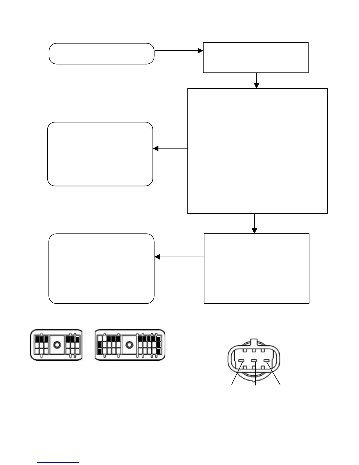
K J H G F E D C B A
H1 Left Front Mod Common
F1 Left Front Mod Exhaust
G1 Left Front Mod Hold
C1 Right Front Mod Common
E1 Right Front Mod Exhaust
D1 Right Front Mod Hold
A1,A2,A3 Ground
B1,K2,K3 Power
F1 Left Rear Mod Common
D1 Left Rear Mod Exhaust
E1 Left Rear Mod Hold
A1 Right Rear Mod Common
C1 Right Rear Mod Exhaust
B1 Right Rear Mod Hold
1
2
3
30-Pin Connector
F E D C B A
18-Pin Connector
1
2
3
Exhaust Common Hold
ABC
Electrical connector on the M-30
™
,
M-22
™
or M-22
™
Modulator
Make repairs to wiring or replace ABS
modulator. Reconnect all connectors
to the EC-30
™
controller and ABS
modulator. Reset fault codes by
briefly holding a magnet in place at
the RESET location of the diagnostic
display. Then rerun the power up
sequence. Go to Section A.
MOD LED and ABS warning lamp
are on.
Turn the ignition off and remove the
30-pin or 18-pin connector from the
EC-30
™
controller.
Dynamic ABS Modulator Faults -
Verify proper modulator activation with
brake pressure applied at power-up
(chuff test) and/or using diagnostic tool.
Check for dragging brakes, dry bearings,
faulty return springs, parking brake
system faults, restricted brake air lines,
over adjusted slacks, out-of-round drums
or damaged/loose tone rings.
Make repairs to ABS modulator
installation or wheel end. Reconnect
all connectors to the EC-30
™
controller
and ABS modulator. Reset fault codes
by briefly holding a magnet in place
at the RESET location of the
diagnostic display. Then rerun the
power up sequence.
Go to Section A.
NO
YES
Static ABS Modulator Faults. For (a) M-30
modulator verify 3.5 to 5.0 OHMS across Hold to
Common connector pins, 3.5 to 5.0 OHMS across
Exhaust to Common connector pins, and 7.0 to 10.0
OHMS across Exhaust to Hold connector pins, or for
(b) M-32 modulator verify 4.9 to 5.5 OHMS across
Hold to Source connector pins, 4.9 to 5.5 OHMS
across Exhaust to Source connector pins, and 9.8
to 11.0 OHMS across Exhaust to Hold connector
pins. Verify no continuity from modulator connector
pins to ground. Verify ignition power is not measured
at any modulator connector pins. Check for corroded
or damaged modulator wiring and connections. If a
circuit fault is found, isolate the area needing repair
by repeating the measurements at all connections in
the ABS modulator circuit.
ABS modulator fault identified?