27
SECTION H - TROUBLESHOOTING WHEEL SPEED SENSORS
1
2
3
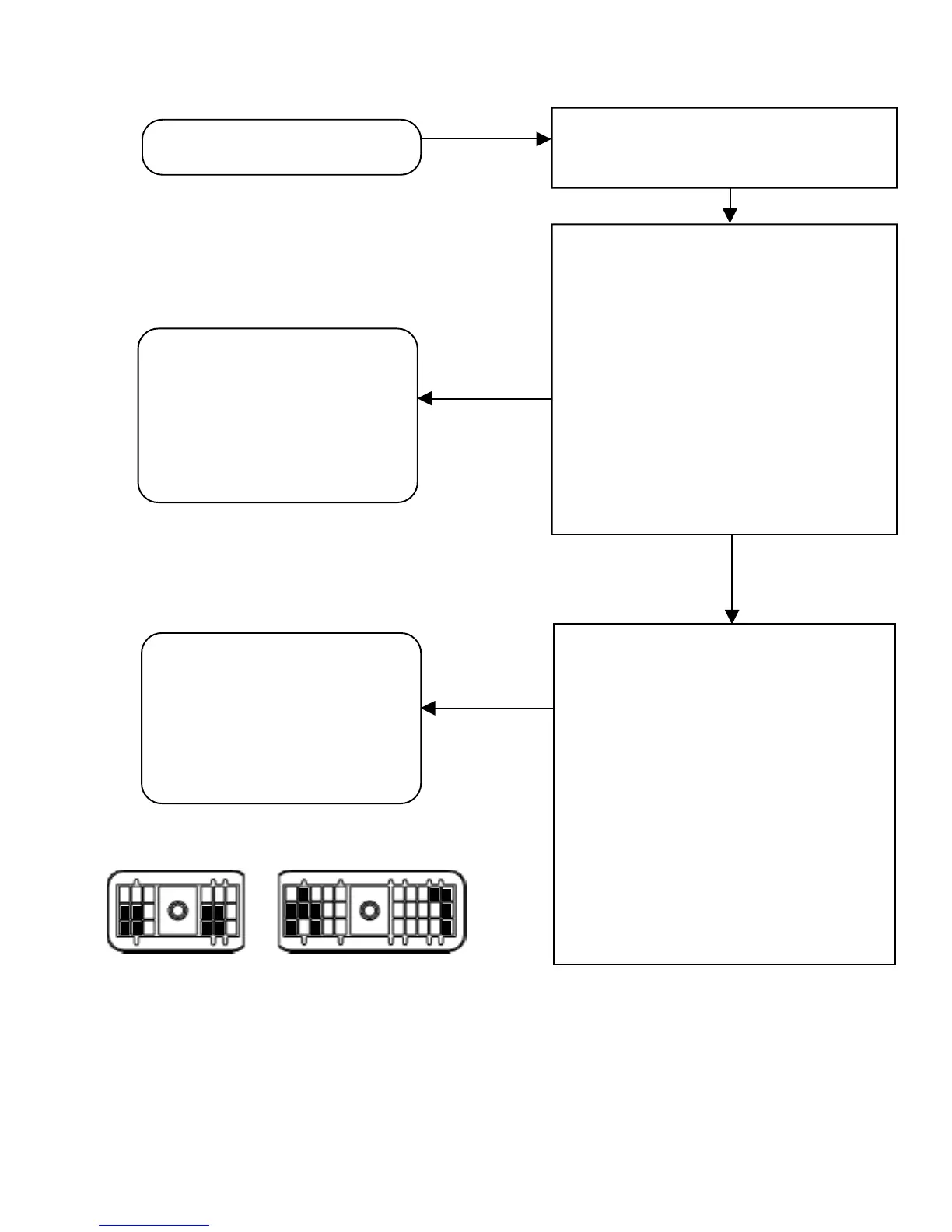
H3 Right Front WS -
H2 Right Front WS +
J2 Left Front WS -
J1 Left Front WS +
A1,A2,A3 Ground
B1,K2,K3 Power
K J H G F E D C B A
30-Pin Connector
B3 Right Mid WS -
B2 Right Mid WS +
C3 Left Mid WS -
C2 Left Mid WS +
E3 Right Rear WS -
E2 Right Rear WS +
F3 Left Rear WS -
F2 Left Rear WS +
F E D C B A
18-Pin Connector
1
2
3
Make repairs to wiring or replace
wheel speed sensor. Reconnect all
connectors to the EC-30
™
controller
and sensor. Reset fault codes by
briefly holding a magnet in place at
the RESET location of the diagnostic
display. Then rerun the power up
sequence. Go to Section A.
SEN LED and ABS warning lamp
are on.
Turn ignition off and remove the 30-pin or
18-pin connector from the EC-30
™
controller.
Static Wheel Speed Sensor Faults - Using
a volt/ohm meter to measure the connector
pins of the faulted sensor, verify 1500-2500
OHMS across sensor connector pins.
Verify no continuity from sensor connector
pins to ground. Verify ignition power is not
measured at either sensor connector pins.
Check for corroded or damaged sensor and
ECU wiring and connectors. Verify proper
sensor lead routing and clamping. If a
circuit fault is found, isolate the area
needing repair by repeating the
measurements at all connections in the
wheel speed sensor circuit.
Wheel speed sensor fault identified?
Dynamic Wheel Speed Sensor Faults -
Rotate the effected wheel and verify for (a)
WS-20 speed sensors, a minimum of 0.8 VAC
sensor output @ 1 RPS across the wheel speed
sensor pins, or (b) for WS-24 speed sensors, a
minimum of 0.250 VAC @ 0.5 RPS. A properly
positioned sensor can output more than 2.0 VAC
@ 1 RPS. Adjust speed sensors to contact
tone ring. Verify condition and retention force
of sensor clips. Verify proper sensor lead
routing and clamping. Verify sensor leads are
twisted pair. Verify condition of tone ring
mounting and teeth. Verify proper number of
tone ring teeth per sensed wheel. Verify proper
adjustment of wheel bearings. Verify condition
of foundation brakes.
Make repairs to wheel speed sensor
installation. Reconnect all connectors
to the EC-30
™
controller and sensor.
Reset fault codes by briefly holding a
magnet in place at the RESET location
of the diagnostic display. Then rerun
the power up sequence.
Go to Section A.
NO
YES