24
Troubleshooting: Using Hand-Held or
PC-Based Diagnostic Tools
Bendix
®
RDU
™
(Remote Diagnostic Unit)
The Bendix
®
RDU
™
tool provides the technician with
a visual indication of Antilock Braking System (ABS)
component Diagnostic Trouble Code (DTC) information.
The RDU
™
tool is specically designed for use with Bendix
®
ABS systems and Bendix makes no claims for its operation
and/or usability with other brands of ABS systems.
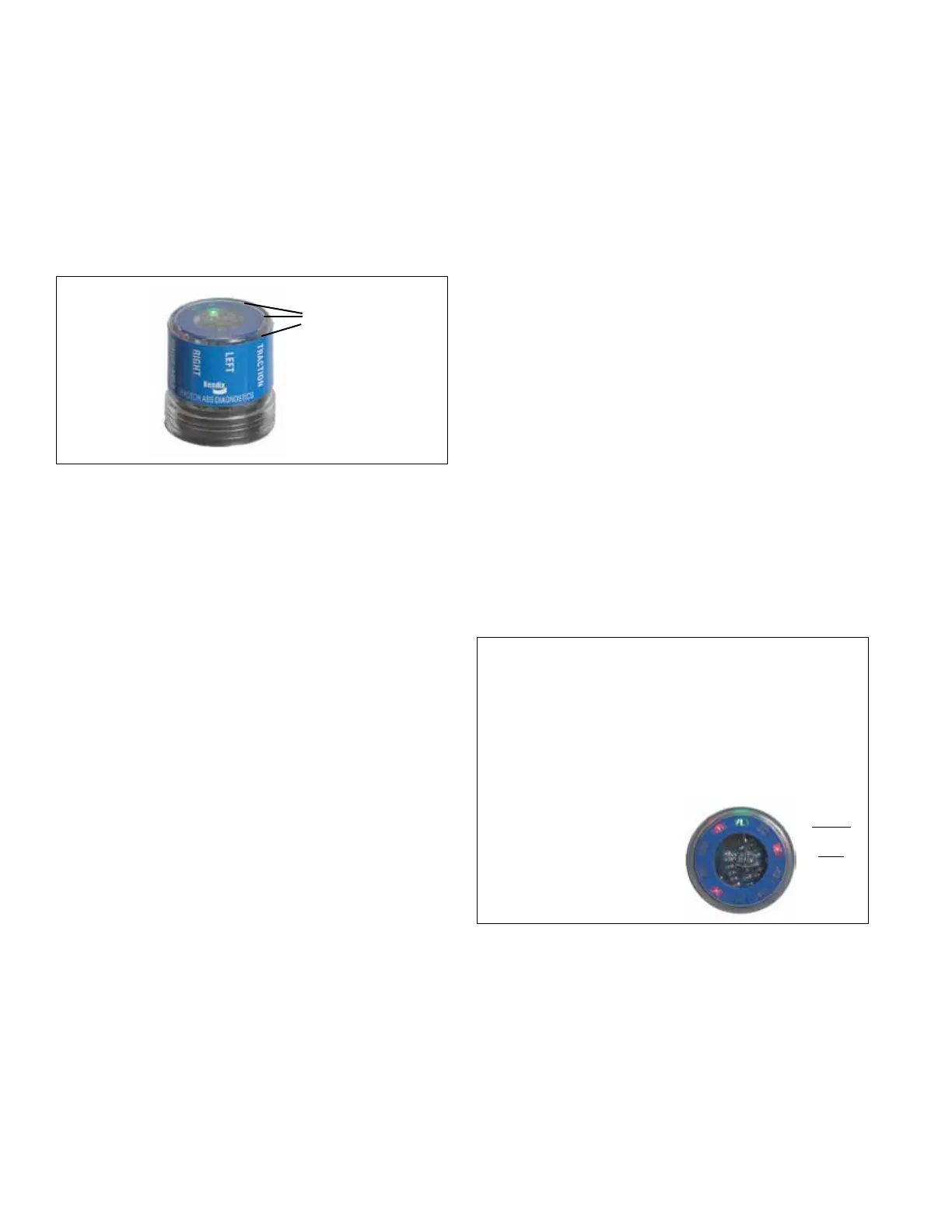
FIGURE 15 - THE BENDIX
®
REMOTE DIAGNOSTIC UNIT
LED lights
illuminate
Diagnostic
Trouble
Codes
(10 locations
in total)
Features of the Bendix
®
RDU
™
Tool
The RDU
™
tool attaches to the 9 pin diagnostic connector
in the cab of the vehicle. An adapter cable (Bendix part
number 801872) is available to connect the RDU to vehicles
with a 6-pin diagnostic connector.
The RDU
™
tool allows the technician to:
• Troubleshoot ABS system component problems using
Diagnostic Trouble Code reporting via LEDs.
• Reset Diagnostic Trouble Codes on Bendix
®
ABS ECUs
by holding a magnet over the reset in the center of the
RDU
™
tool for less than 6 seconds.
• Enter the Self-Conguration Mode used by Bendix
®
ABS ECUs by holding a magnet over the reset area for
greater than 6 seconds but less than 30 seconds.
How the Bendix
®
RDU
™
Operates
See Figure 13 for typical vehicle connector locations.
When the RDU
™
tool is plugged into the diagnostic
connector, all the LEDs will illuminate, and the green LED
will ash 4 times to indicate communications have been
established.
If the ABS ECU has no active Diagnostic Trouble Codes,
only the green LED will remain illuminated.
If the ABS ECU has at least one active Diagnostic
Trouble Code the RDU
™
tool displays the rst diagnostic
trouble code by illuminating the red LEDs, indicating the
malfunctioning ABS component and its location on the
vehicle. (See Figure 15.) If there are multiple diagnostic
trouble codes on the ABS system, the RDU
™
tool will
display one diagnostic trouble code rst, then once that
Diagnostic Trouble Code has been repaired and cleared,
the next code will be displayed.
Typical Combination Diagnostic Trouble Codes are:
• Right steer sensor
• Left steer sensor
• Right drive sensor
• Left drive sensor
• Right additional sensor
• Left additional sensor
• Right steer modulator
• Left steer modulator
• Right drive modulator
• Left drive modulator
• Right additional
modulator
• Left additional modulator
• Rear Axle Traction
modulator
• ECU
• Engine serial
communication
• MOD red LED illuminated, shows the "Common"
connection of one or more modulators is shorted to
battery or ground
• VLT (Flashing indicates either over- or under-voltage
condition)
To pinpoint the root cause and to ensure the system
diagnostic trouble code is properly corrected the rst time,
additional troubleshooting may be necessary. Note: The
RDU is not capable of diagnosing ESP-specic diagnostic
trouble codes including additional sensors: steering angle
sensors, yaw sensors, pressure sensors, or modulator
valves (trailer pressure modulating valves or front axle
traction control valves.)
LED DIAGNOSTIC TROUBLE CODES
FIGURE 16 - DIAGNOSTIC TROUBLE CODES
LFT - Left
RHT - Right
DRV - Drive Axle
ADD - Additional
STR - Steer Axle
VLT - Power
ECU - ABS Controller
SEN - Wheel Speed
Sensor
MOD - Pressure Modulator
Valve
TRC - Traction Control
Example: If the
Diagnostic Trouble Code
is "Right Steer Axle
Sensor", the RDU
™
unit
will display one green and
three red LEDs
LEDs
Green
VLT
Red
SEN
STR
RHT