_____________________________________________________________________________________
8300-088 AeroCruze 110 Installation Manual
Rev 1 Page 7
© Honeywell International Inc. Do not copy without express permission of Honeywell.
extended parallel to the primary cable is approximately 3/16” from the primary cable. If the
primary control travel does not exceed 5” the cable locking pin will be 180 away from the
point at which the cable leaves the capstan. When the primary control is at the neutral point
this means the total cable wrap around the capstan is 360. If the primary control travel is
greater than 5” the cable wrap is 720and the pin is adjacent to the output point when the
primary control is at the neutral point.
The cable clamps when properly installed will not slip and thus get loose, but it is desirable to
NICO press or swedge a fitting on to the cable so as to provide added assurance that the cable
will not become slack. If the bridle cable is not sufficiently tight there will be lost motion in the
autopilot drive. This will result in hunting (oscillation).
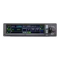
4 CONTROLLER INSTALLATION
4.1 Mounting Considerations
The xCruze 110 autopilot controller unit is designed to mount in the aircraft instrument panel within
view and reach of the pilot. Maximum recommended viewing angle should be no more than 20 deg. The
maximum mounting angle the xCruze 110 can accommodate is 10 degrees longitudinal (pitch) axis and 0
degrees lateral (roll or yaw) axis. The location should be such that the controller unit is not blocked by
the glare shield on top, or by the throttles, control yoke, etc. on the bottom. Use aircraft installation
standards for mounting and support of the controller.
4.2 Wiring Considerations
Use AWG #24 or larger wire for all connections unless otherwise specified. The standard solder pin
contacts supplied in the connector kit are compatible with up to AWG #18 wire. In cases where some
installations have more than one component sharing a common circuit breaker, sizing and wire gauge is
based on length of wiring and current draw on units. In these cases, a larger gauge wire such as AWG
#20 may be needed for power connections. Do not attach any wires to the outside of the programmer
or route high current wires within six (6) inch of the controller. Ensure that routing of the wiring is not
exposed to sources of heat, RF or EMI interference. Check that there is ample space for the cabling and
mating connectors. Avoid sharp bends in cabling and routing near aircraft control cables. Do not route
the COM antenna coax near any autopilot components.
4.3 Pitot and Static Connections
All multi-servo TruTrak autopilots require connections to the pitot and static lines. The ports on the back
of the autopilot are standard 1/8 NPT size. A single wrap of thread tape is recommended. The
preferred method of this connection would be tee fittings near the aircraft’s altimeter. The static line for
the autopilot requires due care in its construction, as excessive lag or insufficient static orifices can
cause the autopilot to oscillate (hunt) in pitch. Although there is compensation within the autopilot
sufficient to handle moderate amounts of lag, the importance of a good static port and line cannot be
overstated. In some cases, problems can be caused by having a large number of devices (including the
autopilot) connected to a single, insufficient, static port. In other cases, the static line itself is adequate
but there are one or more devices connected to the same line, one of which has a large static reservoir.