_____________________________________________________________________________________
8300-088 AeroCruze 110 Installation Manual
Rev 1 Page 9
© Honeywell International Inc. Do not copy without express permission of Honeywell.
6 ELECTRICAL PIN INFORMATION
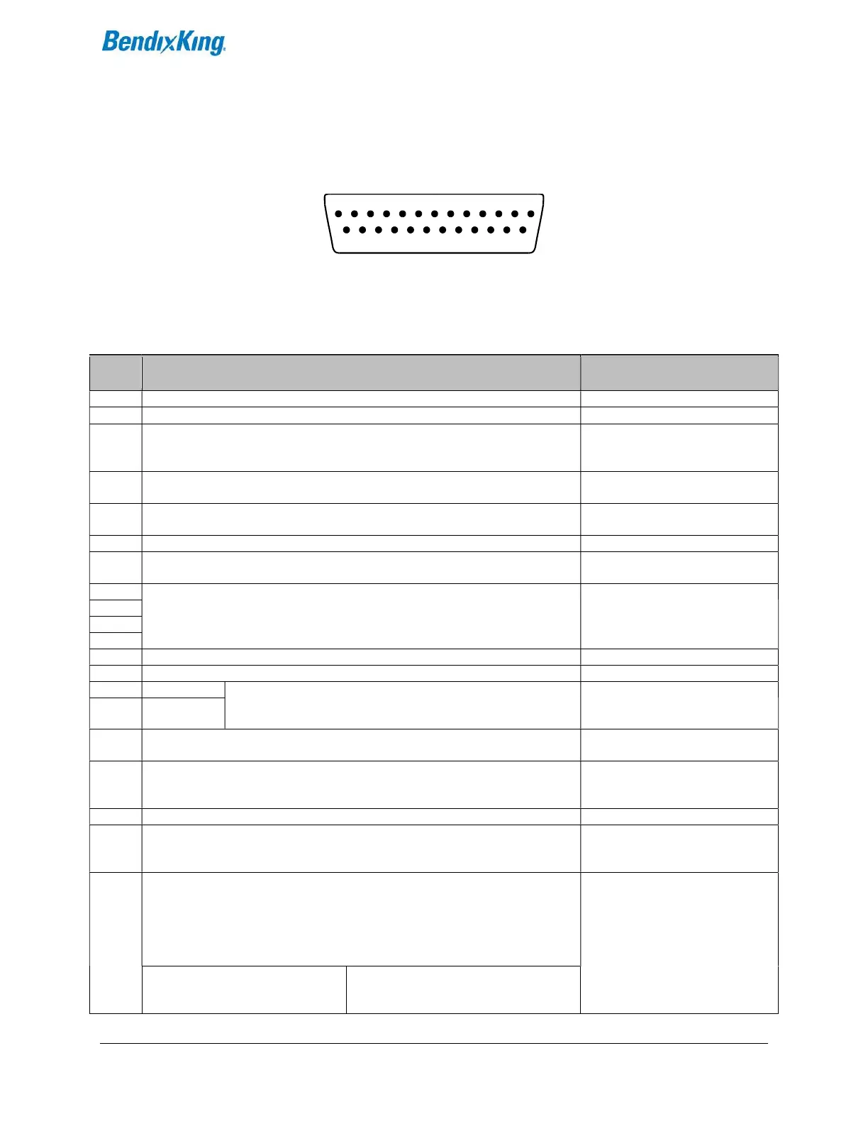
The table below provides a brief explanation of each pin function on the main 25-pin connector P101.
Figure 6-1 Rear 25-Pin Connector P101 Viewed from rear of unit
Table 6-1 P101 Pin Connections
P101
Pin
Function Notes
1 Used for external Emergency AP Level button connection.
2 Used for external Emergency AP Level button connection.
3 Control Wheel Switch. Connect as shown in wiring diagram to a SPST momentary
switch located remotely to the autopilot for convenient engage/disengage
function.
4 Pitch Servo Torque Control. A signal from the autopilot to the pitch servo which
sets the amount of torque to be delivered by the servo.
5 Pitch Servo Trim Sensor. A signal from the pitch servo to the autopilot which
indicates an out-of-trim condition and its direction.
6 Unused.
7 RS-232 Output. Output to G3X/AFS-5000 series Required for integrated control
mode.
8 Pitch Servo control lines. These lines cause the stepper motor in the pitch servo
to run in the appropriate direction at the desired velocity. They are small-signal
lines and do not have any substantial current-carrying capability or require any
special shielding. Connect to pitch servo as shown on wiring diagram.
9
10
11
12 Yaw Damper option.
13 Ground Connection. Provide #20 AWG to common grounding point.
14 ARINC-A Digital differential signals from Garmin, Sierra, or other panel-
mount receiver which provide directional steering commands
(GPSS, GPSV) to autopilot
IFR GPS or EFIS connection
15 ARINC-B
16 Roll Servo Torque Control. A signal from the autopilot to the roll (aileron) servo
which sets the amount of torque to be delivered by the servo.
17 Primary Serial Input. Baud rate selectable 1200, 2400, 4800 or 9600 baud.
Automatically decodes NMEA-0183, Garmin Aviation Format, or Apollo/UPSAT
Moving-Map or GPSS format. Provides directional reference to the autopilot.
18 Auxiliary RS-232 Input. Presently unused.
19 Autopilot Master (+12 to +28 V DC). The autopilot itself draws less than 0.5
ampere. Most of the current required by the autopilot system is used by the
servos (up to 2A per servo).
20
21
22
23
Roll (aileron) Servo control lines. These lines cause the stepping motor in the roll
servo to run in the appropriate direction at the desired velocity. They are small-
signal lines and do not have any substantial current-carrying capability or require
any special shielding. Connect to roll servo as shown on wiring diagram.
Reverse servo direction if
necessary by swapping wires on
pins 20 and 21. See note 2 on
wiring diagram.
Wiring to roll servo J201 Direction of servo arm / capstan rotation
(as viewed from face of the servo body)
for RIGHT aileron
1
20 21 22 23 24 25
2 3 4 5 6 7 8 9 10 11 12 13
14 15 16 17 18 19