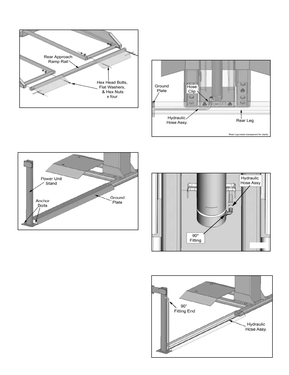
3. Bolt on the Rear Approach Ramp Rail as shown below.
(See Fig. 7.3)
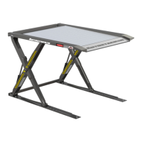
STEP 8
(Installing the Power Unit Stand)
1. Using the Ground plate and chalk line as a guide.
Anchor the Power Unit Stand using Concrete Anchors.
(See Fig. 8.1)
Note: It is helpful to leave the Anchor Bolt Nut on the
Ground Plate loose until after routing of the Hydraulic
Hose and Safety Cable.
STEP 9
(Hydraulic Hose Routing)
1. Route the Hydraulic Hose (Straight End) through the
Ground Plate and through the Rear Leg. Route the Hydraulic
Hose through the rear of the Column, through the hose clips.
(See Fig. 9.1)
2. Install the 90* fitting into the Cylinder port. Use Teflon
Tape on the Pipe Fitting side only. Connect the straight
Hydraulic Hose Fitting end to the Cylinder Fitting. DO NOT
use Teflon tape or any other sealant on the JIC Fittings.
(See Fig 9.2)
3. Route the Hydraulic Hose Assembly through the
Ground Plate and up the Power Unit stand to the Power
Unit Mounting Bracket. (See Fig. 9.3)
12
Fig. 7.3
Fig. 9.1
Fig. 8.1
Fig. 9.2
Fig. 9.3