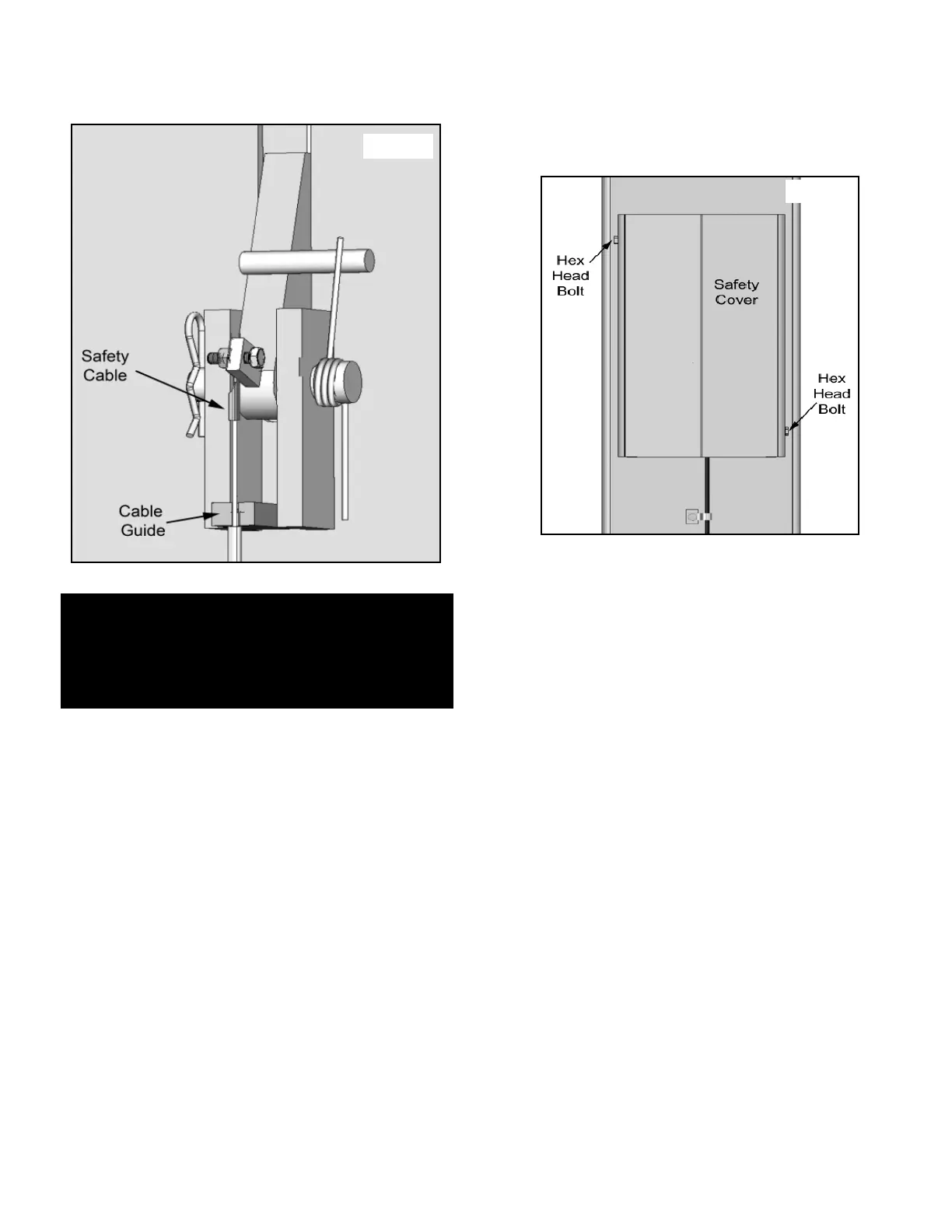
4. Route the Safety Cable Assembly through the Cable
Guide. Bolt the Eyelet end though the Hole in the Safety
and tighten. (See Fig. 11.4)
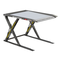
STEP 12
(Installing Safety and Hose Covers)
1. After the lift has been checked for proper operation, install
the Safety Lock Cover. (See Fig. 12.1)
14
Fig. 11.4
NOTE:
THE SAFETY ASSEMBLY AND SAFETY CABLE
MUST BE ADJUSTED AFTER THE POWER UNIT IS
HOOKED UP AND BEFORE ANY VEHICLES ARE
LIFTED TO ENSURE PROPER OPERATION.
Fig. 12.1