7
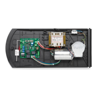
DA.24V/CP.EVA Control Unit
Control unit for 24Vdc motors with power not exceeding 120W to control road barriers.
GENERAL WARNINGS
a) The wire connections and the operating logic should be in compliance with regulations in force.
b) The cables featuring different voltage should be physically detached, or adequately insulated by an
additional insulation of at least 1 mm.
c) The cables should be further fastened in proximity to the terminals.
d) Check all connections before powering the unit.
e) Check that setting of the Dip-switches are the required ones.
f) The Normally Closed (N.C.) contacts which are not in use should be short-circuited.
INPUT/OUTPUT FUNCTIONS
N° of terminals Function Description
1-2 Power supply Input, 230Vac 50Hz (1-Neutral/2-Phase)
4-5 Motor 24Vdc Connection to motor, 24Vdc
6-7 Flasher Flasher connection, 24Vac 40W max.
8-9 24 Vac
Output, accessories power supply - 24Vac/0.5A max.
IMPORTANT: If the battery charger board CB.24V is installed,
the output (without mains power connected) has a 24Vdc po-
larised voltage. Make sure the devices are correctly connected
(i.e. 8:+24Vdc - 9:-24Vdc).
10-11 Road barrier lights
Connection of barrier beam lights, 24Vdc (10+/11+) -200mA
max (equal to approx. 6 lights).
12 COM Common to all control inputs.
13 STOP Input, STOP push-button (N.C. contact)
14 PHOT
Input, safety devices connection, N.C. contact
(ex. Photocells)
15 OPEN Input, OPEN push-button (N.O. contact)
16 CLOSE Input, CLOSE push-button (N.O. contact)
17 Step-by-Step Input, step-by-step push-button (N.O. contact)
18 COM Common, limit switches.
19 SWC
Input, CLOSURE limit switch (N.C. contact).
When this contact is opened, power supply to the motor is cut-
off at the end of the road barrier closing operation.
20 SWO-R
Input, braking limit switch in the opening phase (N.C. contact).
When this contact is opened, braking starts during the barrier
opening phase.
21 SWC-R
Input, braking limit switch in the closing phase (N.C. contact).
When this contact is opened, braking starts during the barrier
closing phase.
24-25 Antenna
Connection of the antenna radio receiver removable board
(24-signal/25-screen).
28-29 Radio 2
nd
Ch Output, N.O. contact of the second radio channel.
VAUX-0-VMOT Secondary Connection of the transformer secondary winding
L1-N1 Primary Connection of the transformer primary winding
J3 Radio receiver Removable connector for radio receiver.
 Loading...