f) Adjust trimmers LIM-A and LIM-C, which limit the maximum current to the motor.
LIM-A to regulate current in the opening phase, LIM-C to regulate current in the closing phase.
Caution
To power the control unit with buffer batteries it is mandatory to use the battery charger which has to be con-
nected to the special connector (J3).
Buffer batteries
• If the buffer batteries are being used (2x12V in series), to shutdown completely all power to the control unit just
disconnect terminal “+BATT, -BATT” (33, 34).
• The battery charger needs a few days to completely recharge the batteries.
• During battery operation, the motor will run at a slightly slower speed than normal, regardless of the battery
charge.
• Correct battery connections:
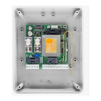
Input/Output functions
1,2 Input 230Vac Power supply of the control unit 230Vac, 50Hz
3,4 Primary output Output to primary circuit of transformer 220V/ 0-18V/0-26Vac
5,6 Serial input Input of serial communication with various road barriers (5=GND; 6=+)
7,8 Secondary 18V input Input from secondary circuit of transformer 0-18Vac
9,10 Secondary 26V input I Input from secondary circuit of transformer 0-26Vac
11,12 24Vdc output Stabilised 24Vdc output for auxiliary power supply
(11= GND; 12=+24V)
13,14 Channel 2 output N.O. contact actuated by second channel of radio control
15,16 Antenna Input Antenna connection for radio control receiver board
(15=+ant; 16=GND))
17,18 Electrolock output Output terminals for electrolock (17=+ser; 18=-ser)
19,20 LP1 output Output terminals for beacon. 24V lamp - max 10W
21,20 SBA output Output terminals for “Barrier Open Light”. 24V lamp - max. 10W.
22 Input CHIUDE (CLOSE) N.O. contact
23 Input APRE (OPEN) N.O. contact
24 P.P. input Step by Step input. Connected in parallel with radio control output. N.O.
contact
25 Input STOP N.C. contact
26 Input FC Input, closing limit switch. N.C. contact
27 Input FA Input, opening limit switch. N.C. contact
28 Input FTC For connection to photocell output contact. N.C. contact.
29 Input for safety edge or
device.
When it trips the motor changes direction for 1 second if it is in the close
cycle. N.C. contact.
30 Output COM Common terminal for all inputs.
31,32 Output Motor To the motor, 24Vdc
33,34
35,36
Input battery Direct connection for buffer battery (2x12V), (33= +24V; 34,35,36= GND)
J1 Connector for radio control receiver board
J3 Connector for battery charger board