3 135113 Rev C 4/2/18
STEP 2 – DETERMINE SIDE 1 AND SIDE 2 OF THE UNIT
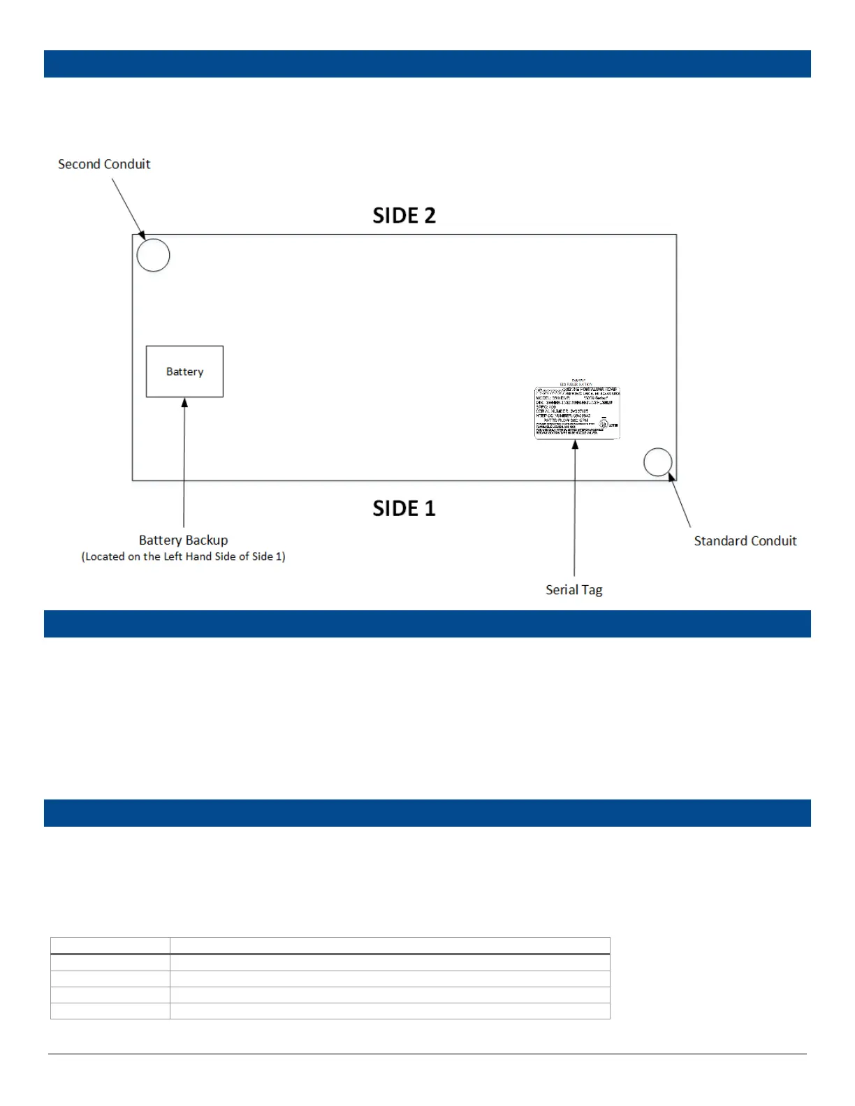
Before placing, the unit onto the island verify the proper orientation and product pipe location of the unit. A common error is placing the unit on
the island backwards resulting in a longer installation time.
Side 1 of the dispenser has the Battery located on the left hand side. The optional junction box is also located on Side 1 in the lower (hydraulics)
area.
STEP 3 –DETERMINE THE TYPE OF DISPENSER SUMP
Before placing a 3000 Series Electronic Dispenser onto an island, determine what type of dispenser sump is used and follow the original
manufacturer’s installation instructions. Review the Bennett 3000 Series Electronic Dispenser Footprint for your unit and get the measurements of
the existing or new dispenser sump to determine if any adjustments are needed prior to mounting the unit onto the island.
BENNETT RECOMMENDED DISPENSER SUMPS FOR THE 3000 SERIES ELECTRONIC DISPENSER
STEP 4 – DISPENSER BASE (PRODUCT PIPING)
Refer to the section below to determine the product piping required for your dispenser.
Step 1: Determine the type of supply line needed from the model number’s 7th position on the serial label.
R = Remote Dispensers will require a submerged pump and pressurized supply line for each product.
S = Suction Pumps will require a suction supply line for each product.
Step 2: Determine the number of product pipes required by finding the model number below.
Product Supply Lines Required
Use 1 product line plumbed to position 1
Use 1 product line plumbed to position 1
Use 1 product line plumbed to position 1 and 1 product line plumbed to position 2
Use 1 product line plumbed to position 1 and 1 product line plumbed to position 2