


T
twhiteAug 15, 2025
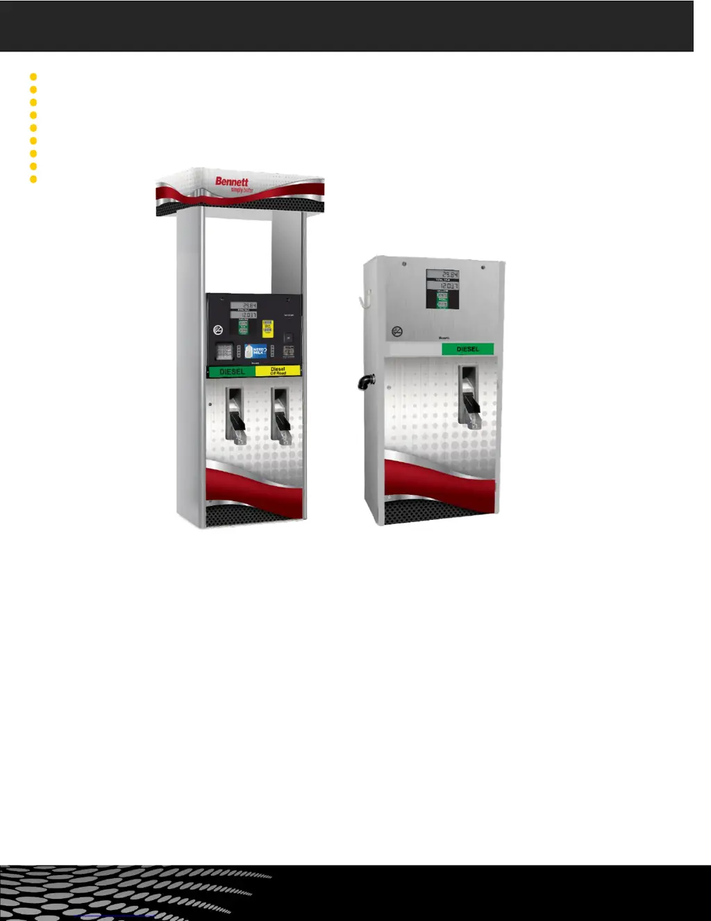
What to do if my Bennett 3000 has no display?
- BBrenda HowellAug 15, 2025
If your Bennett Dispenser display is blank, there are a few things you can check: First, ensure the breaker is turned on. Next, test fuse F1 on the CPU; if it's blown, replace it with a 3A slow blow fuse. Also, measure the voltage on input terminal TS1 pins 1 and 2 to see if the power wire is broken or disconnected. Inspect the quick disconnect terminal strip from the board for any damage. Finally, try replacing the CPU with a known good one.


