Bennett 3000 Spec 300 Series Instruction Manual Service & Troubleshooting
40
COMPONENT DESCRIPTION
The following section provides a detailed description of the connections to the terminal strips and pinouts with a detailed description of
each component and the interface characteristics at each terminal on the 719 CPU board. Note: Voltage readings can be taken right on
the terminal strip connector pins.
WARNING: THE INTRINSICALLY SAFE BARRIER HAS SPECIAL FUSES THAT ARE SOLDERED ONTO THE BOARD AND CANNOT
BE REPLACED IN THE FIELD. IF A FUSE HAS BLOWN ON THE BOARD, IT MUST BE SENT BACK TO BENNETT PUMP
FOR REPAIR. IF YOU TRY TO FIELD REPAIR THIS BOARD, INJURY OR DEATH COULD RESULT DUE TO AN
EXPLOSION OR FIRE AT THE PUMP.
The following is a description of the connections to the terminal strips and pinouts of all the connections on the 719 circuit board.
BT1 Battery
Note: The battery life will be shortened if the upper dispenser doors are left open for an extended amount of time.
This assumes that the dispenser has the optional door sensor switches (Mexico Use Only).
The BT1 3.0 Volt Lithium Button Cell retains totals and programmed information in the system memory during power
failures.
S1 Electronic Calibration (E-Cal) Switch
The Electronic Calibration Switch is used to perform electronic calibration of the meter. There is a stud provided to
prevent an unauthorized user from moving the switch into the Calibration Mode. This stud must be sealed in place to
restrict tampering with the calibration settings and ATC measurements. Programming values in Modes 27 and 99
cannot be altered with the switch in operate mode. If the customer attempts to fuel with the switch in the calibrate
position then an error 74 will be displayed.
S2 Power Switch
WARNING: To prevent electric shock, make sure the current is off at the circuit breaker(s) and the breaker is locked out
before doing any repairs or maintenance to the dispenser.
DANGER: INCOMING AC POWER AT TS1 WILL REMAIN ACTIVE IF THE MAIN CIRCUIT BREAKER(S) ARE
NOT TURNED OFF.
A Power Switch is used to apply or to remove power from the dispenser. When the switch is in the off position, main
power is removed from the electronic circuit board.
S3 Battery Kill Switch
Note: After powering the dispenser off wait, no less than five seconds before pressing the battery disconnect switch.
A push button switch is used to kill the battery backup if necessary. This switch can be used to override the 30-second
battery if primary power is lost at the dispenser, or if incoming power drops below 74 volts AC. This switch stays in the up
position by a spring. To “kill” power to the dispenser press down quickly and release. Once the switch is closed, and the
display goes blank, release the switch.
J1 Ethernet Personality Module Port
A 40-position ribbon cable header connects to the Ethernet Personality Module.
J2 Current Loop, RS485, or Pulse Output Personality Module Port
A 30-position ribbon cable header connects to the Current Loop, RS485, or Pulse Output Personality
Module.
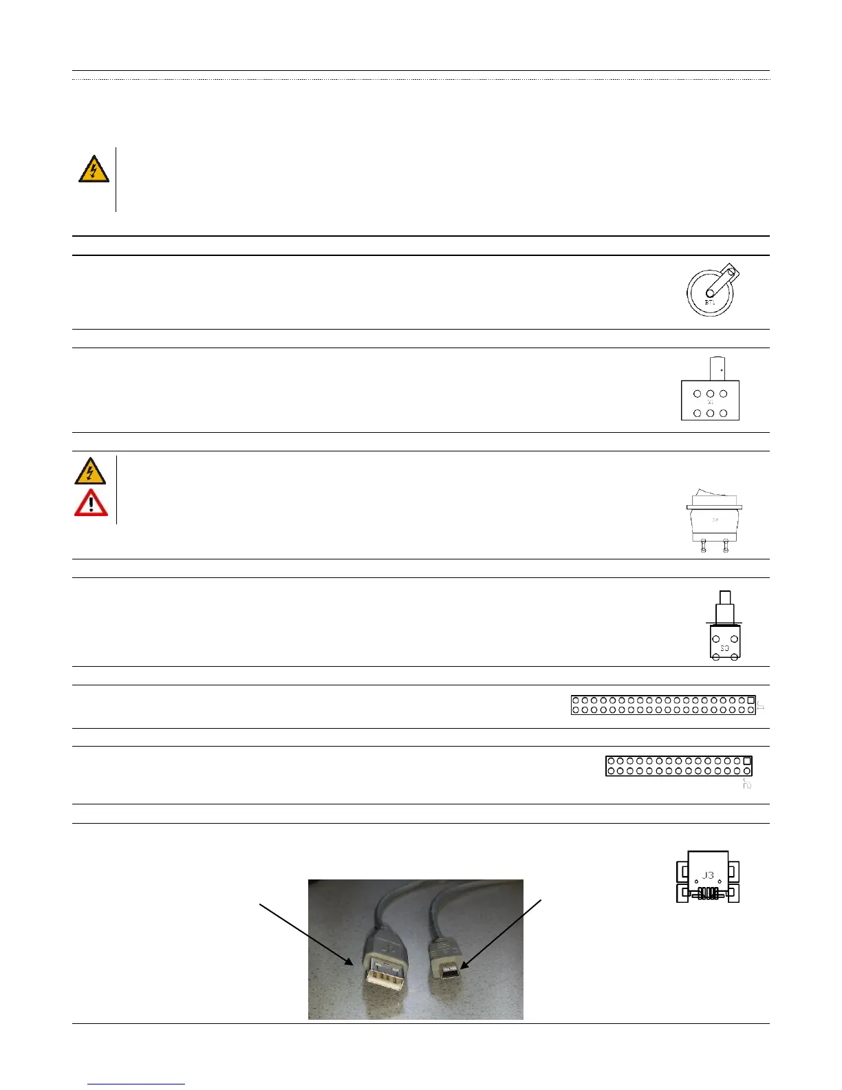
J3 Mini USB Port
A standard Mini USB port is used to connect a mini-USB cable to a laptop used for software updates. Note: For software updates, plug the
mini USB cable into J3 connection. Plug the other end of the mini USB cable into the USB port on the laptop. Call
Bennett Technical Support group for software updates.