Bennett 3000 Spec 300 Series Instruction Manual Service & Troubleshooting
55
HYDRAULIC COMPONENTS
DUAL PHASE PULSERS (STANDARD FLOW)
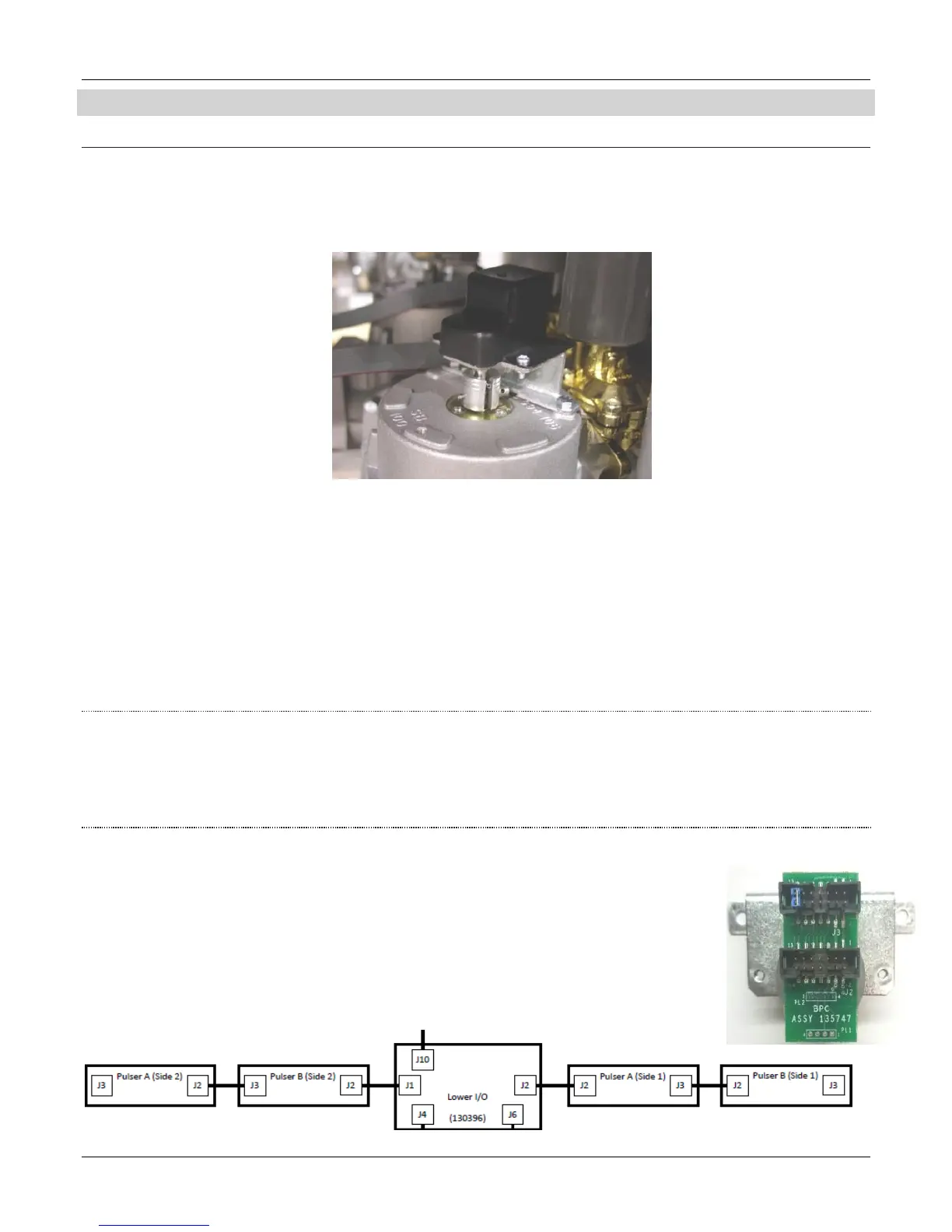
The 3000 series pulsers are dual phase electronics pulsers that pulse at a rate of 1024 pulses per gallon. These pulsers are physically
mounted to the output shaft of the Bennett SB-100 meter. Note: There is one pulser for every meter. As fuel flows through the meter,
the output shaft rotates and turns the pulser. Approximately 8 rotations of the meter represents 1 gallon of fuel. Refer to the Service &
Troubleshooting section for more information.
The pulser is an optically coupled device with a spinning disk with two infrared beams and outputs 2 separate phases of square wave
pulses 90 degrees out of phase with each other. We call these two phases’ phase 1 and phase 2 or “Leading” and “Lagging” phases. These
signals are routed through a ribbon cable connection, in a daisy chain fashion where it connects through the “flame deck” to the barrier
board for that side. There it connects to the CPU board for processing. The pulsers operate off a regulated +5volt dc signal that was
created from a +12volt supply. When the valves are closed and there is no fuel flow, there should be no pulses output from the pulser.
The pulser only generates pulses as it is turning. As it is turned by the output meter shaft it generates pulses, and sends these pulses to
the CPU board through the Barrier Circuit for that hose. The CPU counts the pulses and performs the mathematical computations to
covert this information to a display readout that shows the volume and its corresponding computed currency value on the main display.
The CPU and the pulser works in conjunction with one and another. For example, the CPU first opens the slow flow portion of the 2-stage
valve. At this point, the CPU is making sure that both phases are working. If one of the phases of the pulser is not working, the dispenser
will never come out of slow flow. After nine good pulses are received from both phases, the system opens up the high flow portion of the
2-stage valve and full flow is achieved. Generally, a retail dispenser in fast flow puts out a maximum of 10-12 gallons per minute
maximum due to state and federal regulations.
ERROR CHECKING
The dual phase pulsers allow for error checking. One phase is used to check the other. For example, after pumping 1 gallon of fuel the
CPU should see approximately 1024 pulses from each phase. There is a built in diagnostic where if the CPU sees more than 15
consecutive missing pulses from one or the other of the phases it will stop the sale and post an error message on the display of the side
of the dispenser with the error. Any error that occurs can be cleared by removing and replacing the hose from the nozzle boot. In
addition, if the pulser is disconnected, an error will result.
PULSERS OPERATION
The pulser information is carried on a ribbon cable that connects the pulser to the barrier circuit. This ribbon
cable connects from connector J1 (Side 2) or J2 (Side 1) of the 419 Lower I/O Board, runs through a potted
conduit between the upper portion (electronics area - high voltage) section of the dispenser to the lower
portion (hydraulics area - low voltage) section of the dispenser. This ribbon cable connects to pulser connector
J2 to the first pulser in the loop. Usually this is the “A” product. If there is more than one product (pulser) then
another ribbon cable connects from the first pulser J3 (back) connector to the next pulser J2 (front) connector
and it works like this for the remaining pulsers except for the last pulser for that side in the loop.
Note: On the last pulser, a jumper must be placed across the last set of pins on J3 to identify that pulser as the
last pulser in the loop.