Bennett 3000 Spec 300 Series Instruction Manual Service & Troubleshooting
56
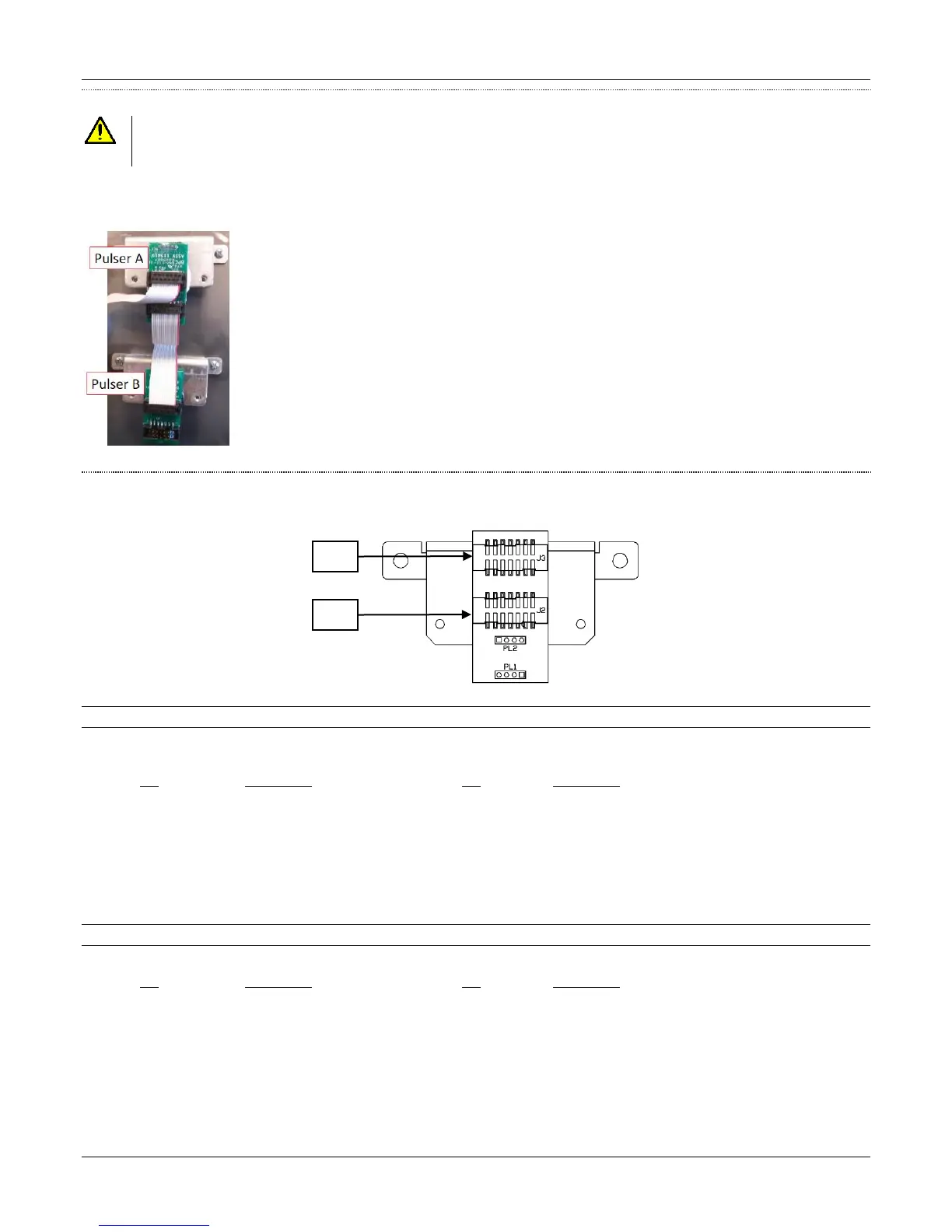
PULSER CONNECTION
CAUTION: WHEN CONNECTING A PULSER NEVER CONNECT A PULSER OR DISCONNECT A PULSER WITHOUT TURNING OFF
THE DISPENSER POWER AND BATTERY. DAMAGE TO THE PULSER OR THE LOWER I/O BOARD CAN OCCUR IF
POWER IS LEFT ON..
The pulsers connect to the Lower I/O board through a ribbon cable in a daisy chain fashion. All of the pulsers for side 1 connect to J2 on
the Lower I/O board and all of the pulsers for side 2 connect to J1 on the Lower I/O Board. The ribbon cable has notches so the cable
cannot be put on backwards.
Pulser for Product A plugs directly into the Lower I/O Board
J2 = Lower I/O Board
J3 = Pulser B
Pulser for Product B plugs directly into Product A’s Pulser
J2 = Pulser A
J3 = Shunt on Pins 13-14
COMPONENT DESCRIPTION
The following is a description of the connectors and pinouts on the pulser circuit board.
J2 Pulser Connection
A 14-position ribbon cable header to connect directly to the 419 Lower I/O Board. This ribbon cable contains +5VDC power and
communication signals for up to four dual phase pulsers.
Pin Description Pin Description
1 +5 VDC 8 Pulser B Lag Input
2 +5 VDC 9 Pulser C Lead Input
3 Ground 10 Pulser C Lag Input
4 Ground 11 Pulser D Lead Input
5 Pulser A Lead Input 12 Pulser D Lag Input
6 Pulser A Lag Input 13 Connection Verification
7 Pulser B Lead Input 14 Connection Verification
J3 Pulser Connection
A 14-position ribbon cable header connection from the first pulser to the next pulser J2 connector.
Pin Description Pin Description
1 +5 VDC 8 Pulser B Lag Input
2 +5 VDC 9 Pulser C Lead Input
3 Ground 10 Pulser C Lag Input
4 Ground 11 Pulser D Lead Input
5 Pulser A Lead Input 12 Pulser D Lag Input
6 Pulser A Lag Input 13 Connection Verification
7 Pulser B Lead Input 14 Connection Verification