Bennett 3000 Spec 300 Series Instruction Manual Installation Instructions
24
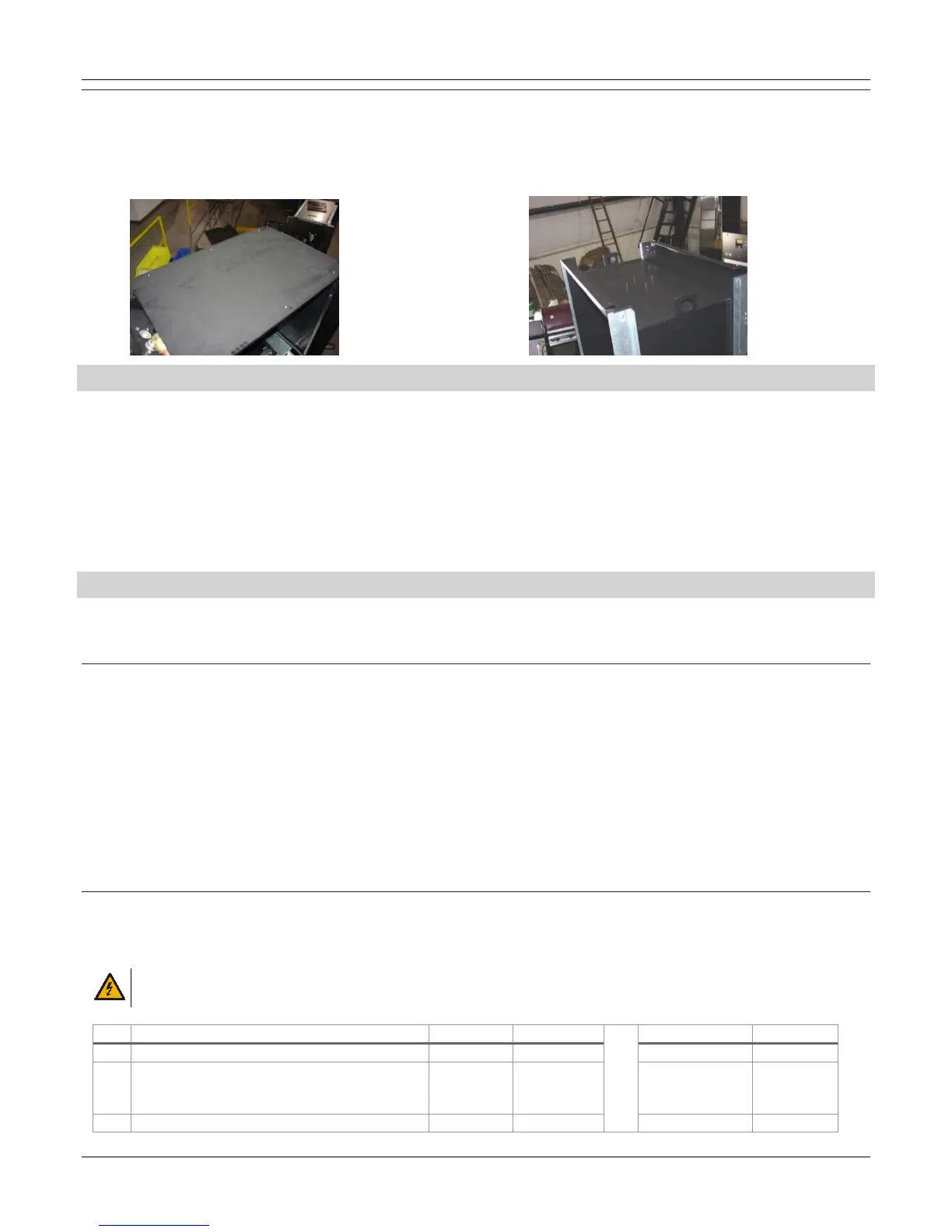
ALTERNATE LIFTING A NEW DISPENSER (HIGH HOSE )
Follow the instructions below for an alternate lifting method for high hose dispenser.
On the high hose models, there are lifting brackets provided in the upper area of the dispenser. Remove the cover that is screwed onto
the top of the dispenser to access the lifting brackets. After the top cover is removed, the lifting brackets can be accessed for lifting the
dispenser overhead.
ANCHORING THE DISPENSER TO THE ISLAND
The dispenser must be bolted firmly to the concrete island. The dispenser base is provided with anchor bolt holes refer to the footprint
drawing for dimensions. Anchor bolts embedded in the concrete island must be no less than ½” (1.3 cm) diameter. The threaded ends of
the anchor bolts should project 1-1/2” (3.8 cm) above the concrete.
On the Low Hose dispenser, 2 anchor bolts required minimum.
On the High Hose dispenser, 4 anchor bolts required minimum in the outer 4 mounting holes.
Refer to the Footprint Drawing used for your dispenser model.
When anchoring the dispenser, always level the dispenser with metal shims before bolting to the island. Place the metal shims at the
location of the anchor bolts so the dispenser frame is not distorted when the anchor bolts are tightened down. Improper shimming that
result in misaligned frames is NOT covered under the Bennett Limited Warranty!
WIRING THE DISPENSER
Follow the sections below for proper equipment grounding, dispenser AC power, and console communication. The 3k dispenser can be
ordered as a one or two hose unit. Note: 1, 2, or 4 hose units have one CPU board an Active 4 unit will have two CPU boards. The CPU
board is where the field wires will connect if the optional junction box is not ordered.
PROPER EQUIPMENT GROUNDING
Grounding provides a path of least resistance for electric current to reduce the risk of electric shock. Grounding is also required to protect
the dispenser’s computer from external electrical noise generating devices. The ground wire connection must provide 1 ohm (or less)
resistance to earth ground.
1. Connect a 12-gauge (minimum), green or green/yellow stranded wire to the grounding terminal on the electronics enclosure deck.
Only one ground wire is required per dispenser.
2. Pull a continuous (one-piece) green or green/yellow, 12 gauge stranded THHN ground wire through the junction box and 3/4” (1.9
cm) conduit and secure at ground lug near the terminal strip in the dispenser’s Junction Box. Terminate the other end at the main
panel breaker box ground bar. Do not terminate at the neutral bar of a sub-panel or rely on metal conduit for this ground
connection. Each dispenser’s grounding post must be within 1-ohm resistance to earth ground potential. You must verify to within 1
ohm of the ground rod. Do not use wire nuts on ground circuits, use only compression type connectors. This is required to initiate
Bennett’s Limited Warranty.
DISPENSER AC POWER
Each dispenser uses one 120V, 50/60 Hz, or 240V, 50/60 Hz circuit for dispenser power. Make sure the power source has the correct
frequency and voltage. Connect the electrical circuit to the terminal strip on the CPU board. Only one dispenser electronics Hot and
Neutral needs to be pulled per dispenser.
WARNING: ALL DISPENSER AC POWER CIRCUITS (FOR REMOTES ONLY) MUST BE ON THE SAME PHASE OR DAMAGE WILL
OCCUR TO THE DISPENSER 719 CPU OR THE SUB-PUMP RELAY BOX.