Bennett 3000 Spec 300 Series Instruction Manual Installation Instructions
25
1. Connect the White (Neutral) 14ga. wire in 120V circuits or the Red 14ga. wire in 240V circuits to terminal 2 of TS2 on the CPU board.
The CPU board is located on the upper electronics deck.
2. Connect the Black (Hot) 14ga. wire to terminal 3 of TS2 on the CPU board.
3. Electronic power must be connected to a dedicated 15-amp neutral breaking circuit breaker. Electronic power for all dispensers at
an installation must be wired to the same AC line phase or damage from cross phasing will result in the remote sub-pump relay
control circuits.
CONSOLE COMMUNICATION
A specific Personality Module is needed for the Current Loop Communication, Generic Current Loop Communication, RS-485
Communication, and Pulse Output for Fleet Management. The dispenser MUST have the correct module for the dispenser to
communicate properly. Refer to the sections below for detailed instructions. Note: Some remote consoles may not be listed.
BENNETT CURRENT LOOP FUEL COMMUNICATION (121982)
To be used with Bennett 515 Box, TMX, Comdata, FIS-CAL, VeriFone Commander, Ruby, and Sapphire remote consoles. Bennett Current
Loop uses a 4-wire protocol.
Use the table below to determine how many wires your communication console requires and the connection points for this type of
communication. Note: Connections will vary depending on the dispenser model and options.
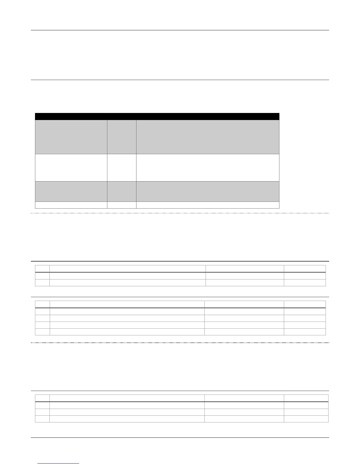
1-SIDED DISPENSER COMMUNICATION = 2 FIELD WIRES (REQUIRED)
Orange #18 Wire - Bennett Current Loop Communication (+positive)
Current Loop Personality Module
Yellow #18 Wire - Bennett Current Loop Communication (-negative)
Current Loop Personality Module
2-SIDED DISPENSER COMMUNICATION = 4 FIELD WIRES (REQUIRED)
Orange #18 Wire - Bennett Current Loop Communication (+ positive)
Current Loop Personality Module
Yellow #18 Wire - Bennett Current Loop Communication (- negative)
Current Loop Personality Module
Orange #18 Wire - Bennett Current Loop Communication (+ positive)
Current Loop Personality Module
Yellow #18 Wire - Bennett Current Loop Communication (- negative)
Current Loop Personality Module
GENERIC CURRENT LOOP FUEL COMMUNICATION (121982)
To be used with Gilbarco Passport, VeriFone Commander, Wayne Fusion, and Wayne Nucleus remote consoles. Generic Current Loop
uses a 2-wire protocol. Note: Refer to the wiring diagram included in the dispenser for wire, shunts, and field jumper wire connections.
Use the tables below to determine how many wires your communication console requires for this type of communication. Note:
Connections will vary depending on the dispenser model and options.
1-SIDED DISPENSER COMMUNICATION = 2 FIELD WIRES AND 1 SHUNT (REQUIRED)
Orange #18 Wire – Generic Current Loop Communication (+ positive)
Current Loop Personality Module
Yellow #18 Wire – Generic Current Loop Communication (- negative)
Current Loop Personality Module
Current Loop Personality Module
COMPATIBLE REMOTE CONSOLES
Bennett 515 Box
TMX
COMDATA
FIS-CAL
VeriFone Commander, Ruby, and Sapphire
Gilbarco Passport
VeriFone Commander
Wayne Fusion
Wayne Nucleus
Note: RS485 uses a 2-wire protocol.
Allied NeXGen remote consoles for retail communication
Fleet Management System for commercial use
To be used with Fleet Management Systems