Bennett 3000 Spec 300 Series Instruction Manual Product Introduction
6
PUMP MOTOR CONTROL REQUIREMENTS
IMPORTANT: SELF-CONTAINED DISPENSER 1HP MOTORS ARE SET AT THE FACTORY FOR 115 V. 2-HP MOTORS (BIG FUELER
SUCTION MODELS) CAN ONLY BE USED AT 230V AND ARE NOT INTERCHANGEABLE.
The Submerged Pump Relay Control Signals are rated at 30 watts, 120VAC, or 240VAC maximum. This signal must be wired to an external
Submerged Pump Relay (with all coil control wires for this relay on the same AC phase) for controlling the submerged pump motors. Use
Red Jacket or FE Petrol Control Box or equivalent.
STANDARD
Standard Remote ................................................................................................................................................................... Submerged Pump
Standard Suction 1-Horse Power Standard 1-Phase ..................................................................................................... 115/230 VAC 50/60 Hz
Standard Suction 1-Horse Power Standard 1-Phase (with prepay valves) .................................................................... 115/230 VAC 50/60 Hz
Standard Suction 1-Horse Power 3-Phase ................................................................................................................................... 380 VAC 50Hz
Suction 1-Horse Power 3-Phase (with prepay valves) ................................................................................................................ 380 VAC 50 Hz
BIG FUELER
Suction 2-Horse Power Standard 1-Phase (with prepay valves) ........................................................................................... 230 VAC 50/60 Hz
Suction 2-Horse Power Standard 3-Phase (with prepay valves) ........................................................................................... 380 VAC 5/600 Hz
OVERVIEW
DANGER: INCOMING AC POWER AT TS1 OF THE 719 CPU BOARD WILL REMAIN ACTIVE IF THE MAIN CIRCUIT BREAKER(S) ARE
NOT TURNED OFF.
WARNING: TO PREVENT ELECTRIC SHOCK, MAKE SURE THE CURRENT IS OFF AT THE CIRCUIT BREAKER(S) AND THE BREAKER IS
LOCKED OUT BEFORE DOING ANY REPAIRS OR MAINTENANCE TO THE DISPENSER.
CAUTION: THE INTRINSIC SAFETY GROUND WIRE MUST BE FIRMLY MOUNTED TO THE DISPENSER CHASSIS TO INSURE
INTRINSIC SAFETY!
Each dispenser uses one 120/240VAC, 50/60 Hz circuit for dispenser power. 110VAC or 230VAC single phase is routed from the main
service panel to the dispenser and connects directly to the 719 CPU or through the optional Junction Box. AC power is then routed
through a filter section of the 719 CPU to eliminate noise spikes and to change the AC voltage over to various DC voltages that are
distributed to several components used within the dispenser.
The DC voltages created are +24, +12, +5, and +3.3 volts DC.
+24 volts – Main Display, Valve Power, Satellite Board
+12 volts – Pump Motor Control, Communication Power, Electromechanical Totalizer (optional)
+5 volts – System Voltage for Circuit Logic
+3.3 volts – CPU Circuit Voltage
There are no test points or adjustments for these voltages. The only voltage that can be measured is the incoming voltage on TS1. The
incoming voltage range can be anywhere from 85-270 VAC.
DOOR KEY LOCKS
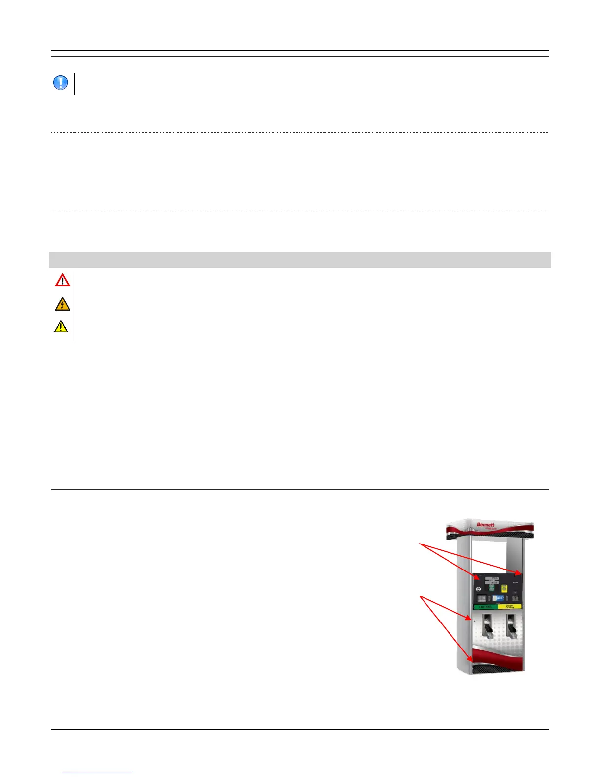
The dual door locks are located on the top edge of the upper electronic cabinet
door and the left edge of the lower door panel as shown in the figure to the
right. The upper door swings down on bottom hinges and the lower door swings
out on the right hand hinges. A universal key is shipped with each dispenser.
Refer to the Operation section for additional information.
The key locks for the electronic door are located on either outside top edge of
the door. The Key locks for the lower door of the 3000 Series are located on the
left side (top and bottom) of the lower door panel. A key is shipped with each
dispenser. The same key is used for all the locks.
To lock the upper door, insert the key in one of the locks and turn clockwise
until it stops. Repeat this step for the other lock. To lock the lower door, turn
the key clockwise until it stops in one of the locks. Repeat this step for the other
lock. To unlock either door, turn the key counterclockwise until it stops.
Note: The upper door swings down on bottom hinges and the lower door
swings out on right hand hinges.
 Loading...


