Bennett 3000 Spec 300 Series Instruction Manual Service & Troubleshooting
41
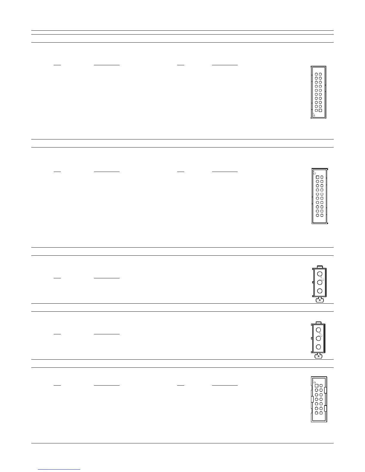
J4 Side 1 Main Display
A 20-position gray ribbon cable header connects to the Main Display. This is used to connect to the Main Display on Side 1 of the
dispenser. Note: (Volume/Volume Twin/Volume Side Mount/Retail/Retail Twin/Retail Side Mount).
Pin Description Pin Description
1 Data Output 11 Display Type Select 0 Input
2 +24VDC 12 Totals Input
3 Load Output 13 Display Type Select 1 Input
4 +24VDC 14 Ground
5 Clock Output 15 Display Type Select 2 Input
6 +12VDC 16 Ground
7 Side 2 Main Totalizer Output 17 Ground
8 +12VDC 18 Ground
9 Side 2 DEF Totalizer Output 19 Ground
10 Recall Input 20 Ground
J5 Side 2 Main Display
A 20-position gray ribbon cable header connects to the Main Display. This is used to connect to the Main Display on Side 2 of the
dispenser.
Pin Description Pin Description
1 Data Output 11 Display Type Select 0 Input
2 +24VDC 12 Totals Input
3 Load Output 13 Display Type Select 1 Input
4 +24VDC 14 Ground
5 Clock Output 15 Display Type Select 2 Input
6 +12VDC 16 Ground
7 Side 1 Main Totalizer Output 17 Ground
8 +12VDC 18 Ground
9 Side 1 DEF Totalizer Output 19 Ground
10 Recall Input 20 Ground
J7 Side 2 Solenoid Valve Output
A 3-wire connection connects to J7 of the 719 CPU for solenoid valve control. Note: The valve type can vary between the solenoid valve
or the proportional valve. Check you dispenser options prior.
Pin Description
1 (black) Solenoid Main Valve Output
2 (yellow) Dribble Valve Output
3 (red) +24VDC
J7 Side 2 Proportional Valve Output
A 3-wire connection connects to J7 of the 719 CPU for proportional valve control. Note: The valve type can vary between the solenoid
valve or the proportional valve. Check you dispenser options prior.
Pin Description
1 No Connect
2 Proportional Valve Control
3 +24VDC Common
J8 Side 2 Local Preset (Optional)
A 14-position header is used to connect the optional local preset keypad.
Pin Description Pin Description
1 ROW 0 Output 8 COL 2 Input
2 ROW 1 Output 9 COL 3 Input
3 ROW 2 Output 10 Recall Input
4 ROW 3 Output 11 Ground
5 ROW 4 Output 12 Ground
6 COL 0 Input 13 Ground
7 COL 1 Input 14 Ground