Bennett 3000 Spec 300 Series Instruction Manual Service & Troubleshooting
42
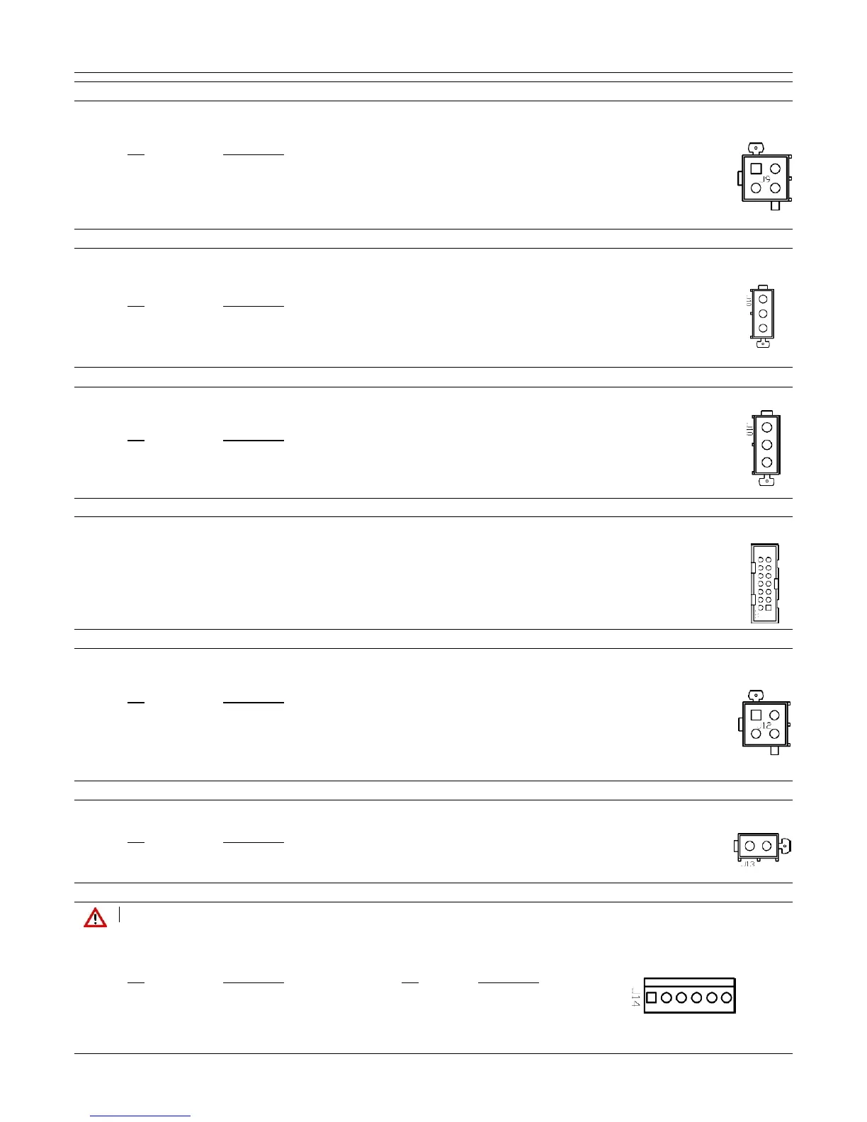
J9 Side 2 Satellite Valve Output
A 4-position header uses wire harness to connect to the Satellite Board for valve control. The Satellite Board controls the valve in the
Master and the valve in the Satellite unit.
Pin Description
1 Main Valve Output
2 Dribble Valve Output
3 +24VDC
4 Ground
J10 Side 1 Solenoid Valve Output
A 3-wire connection connects to J10 of the 719 CPU for side 1 valve control. Note: This valve is also the Side 1 valve for the second
product when the dispenser is configured as 2 side and 2 grades (e.g. diesel + DEF).
Pin Description
1 (black) Main Valve Output
2 (yellow) Dribble Valve Output
3 (red) +24VDC Common
J10 Side 1 Proportional Valve Output
A 3-wire connection connects to J10 of the 719 CPU for side 1 valve control. Note: This valve is also the Side 1 valve for the second
product when the dispenser is configured as 2 side and 2 grades (e.g. diesel + DEF).
Pin Description
1 No Connect
2 Proportional Valve Control
3 +24VDC
J11 Side 1 Local Preset or Managers Keypad
Note: Local preset is optional. If the dispenser does not have, the optional local preset keypad the Manager’s Keypad is used.
Reference the option used in your dispenser.
Local Preset–A 14-position header is used to connect the factory installed local preset keypad.
Managers Keypad - A latched ribbon cable is used to connect to the J11 port of the 719 CPU for dispenser programming.
J12 Side 1 Satellite Valve Output
A 4-position header connect to the J12 connector on the Satellite Board for valve control. The Satellite Board controls the valve in the
Master and a valve in the Satellite unit.
Pin Description
1 Main Valve Output
2 Dribble Valve Output
3 +24VDC
4 Ground
J13 Door Switch Input (Mexico Use Only)
A 2-position door switch is used to connect to the optional door switch.
Pin Description
1 Switch Input
2 Ground
J14 Barrier Output
DANGER: THE BARRIER COVER MUST BE IN PLACE DURING NORMAL OPERATION
This is a 6-position mini universal header and is used to connect the Lower I/O board to the 719 board through an intrinsically safe barrier
on the 719 CPU board.
Pin Description Pin Description
1 +5VDC Output 4 +3.6 VDC Backup
2 RS-485 Data (- negative) 5 Ground
3 RS-485 Data (+ positive) 6 Ground
 Loading...


