Bennett 3000 Spec 300 Series Instruction Manual Service & Troubleshooting
43
J17 Backup Battery
An external +12 VDC lead acid battery connects to J17 for battery backup. When the main power is on the battery, the charging circuit
provides +13.8 VDC to charge the battery. When the battery is “on” the battery supplies 12.6 VDC for the system. Note: Battery recall
during power outage or when pump power is off.
Pin Description
1 Battery (+ positive) - +13.8 volts battery charging. +12.6 volts battery on
2 Battery (- negative) – Direct Current Common (DCC)
3 Ground
4 Ground
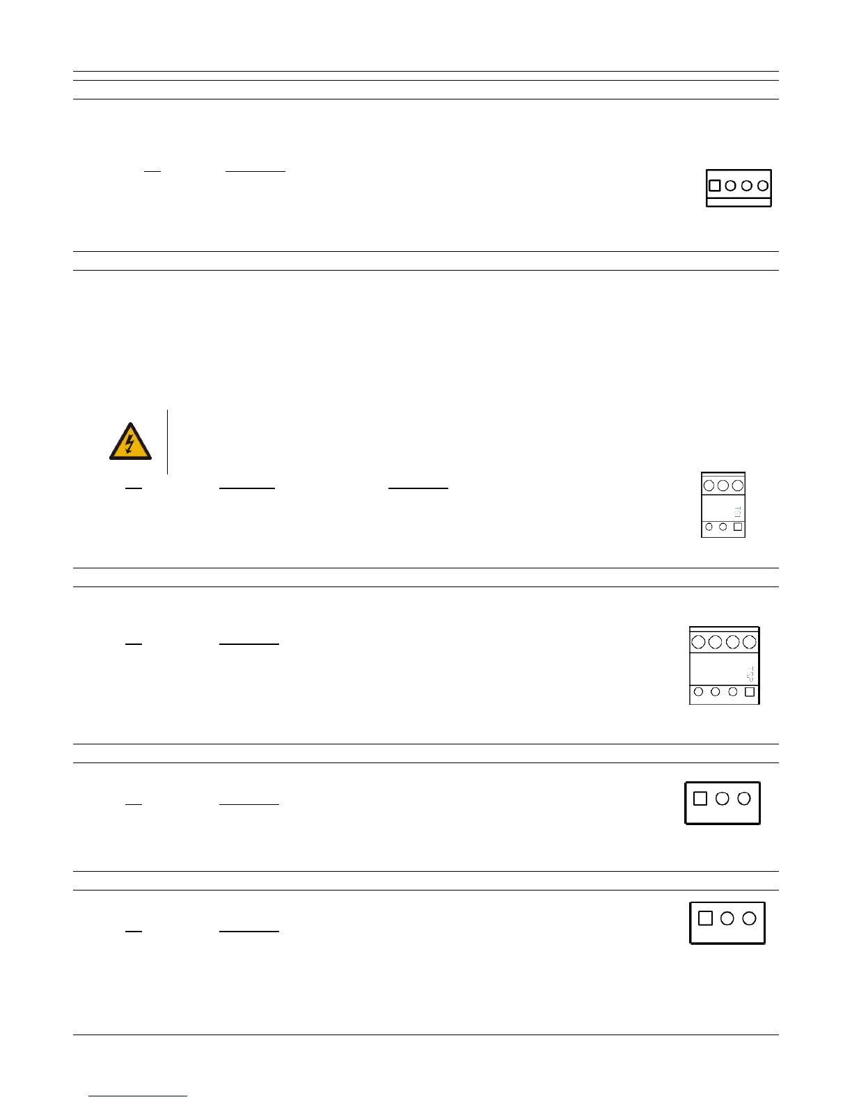
TS1 AC Line Voltage Input
The AC Line Voltage Input supplies power to the dispenser. The different wiring required for 120VAC and 230 VAC applications is shown
in the wiring diagrams provided with the dispenser. Note: There are no jumpers or switches that need to be set for different input power.
Incoming power can range from 270VAC to 85 VAC.
This product must be properly grounded. Each dispenser requires a 12-gauge Green or Green/Yellow Earth Ground Wire. Grounding
provides a path of least resistance for electric current to reduce the risk of electric shock. Ground is also required to protect the 719 CPU
from external electrical noise generating devices. The ground wire connection must provide 1 ohm (or less) resistance to earth ground.
Note: The ground wire must be properly secured directly to the ground bar of the MAIN electrical service panel, not a sub-panel. If a
Junction Box is used, make sure the ground is properly secured to the ground lug.
WARNING: FAILURE TO PROPERLY GROUND THE EQUIPMENT CAN CAUSE INJURY OR DAMAGE TO THE
EQUIPMENT AND WILL VOID THE BENNETT LIMITED WARRANTY. DO NOT USE WIRE NUTS ON
GROUND CIRCUITS, USE ONLY COMPRESSION TYPE CONNECTORS. DO NOT TERMINATE AT THE
NEUTRAL BAR OF A SUB-PANEL OR RELY ON METAL CONDUIT FOR THIS GROUND CONNECTION.
Pin Wire Color Description
1 Green or Green/Yellow Earth Ground
2 White Electronic Power – Line Voltage (L2) or Neutral
3 Black or Red Electronics Power – Line Voltage (L1)
TS2 Pump Motor Control (Submerged or Suction)
A 4-position header is used for input power and to control either the submerged pump motor or the suction pump motor depending on
what model dispenser was ordered.
Pin Description
1 Side 1 Motor Voltage Input
2 Side 1 Switched Motor Voltage Output to Suction Motor or Submerged Pump Relays
3 Side 2 Motor Voltage Input
4 Side 2 Switched Motor Voltage Output to Suction Motor or Submerged Pump
Relays
TS3 Accessory Line Voltage Output
Accessory Line Voltage Output
Pin Description
1 Earth Ground
2 Neutral
3 Line
TS4 Accessory Line Voltage Output
Accessory Line Voltage Output
Pin Description
1 Earth Ground
2 Neutral
3 Line