Bennett 3000 Spec 300 Series Instruction Manual Service & Troubleshooting
52
COMPONENT DESCRIPTION
The following is a description of the terminal strips and pinouts used on the optional Satellite Board.
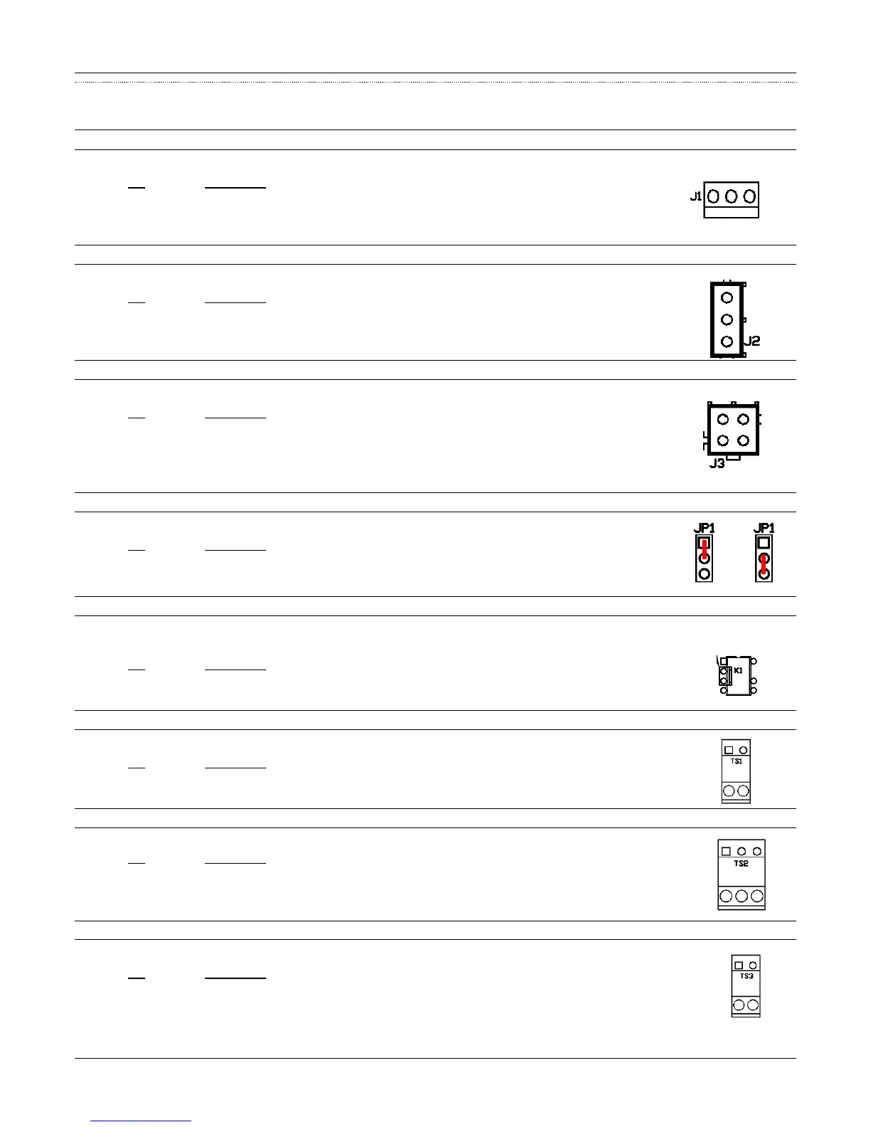
J1 120V AC Power
The J1 connection is a 3-position mini header used to receive 120VAC power from the 719 CPU.
Pin Description
1
2
3
J2 Master Valve Control
The J2 connection is a 3-position mini header used to control the master valve.
Pin Description
1 (black) Main Valve Control (Fast Flow)
2 (yellow) Dribble Valve Control (Slow Flow)
3 (red) +24VDC (Power)
J3 719 CPU Communication
A 4-position mini header connector is used to communicate with the 719 CPU Board (J12 - Side 1 or J9 -Side 2).
Pin Description
1 Main Valve Output
2 Dribble Valve Output
3 +24VDC
4 Ground
JP1 Simultaneous or Exclusive Fueling
The JP1 is a 3-pin jumper used to select simultaneous or exclusive fueling for truck stop applications.
Pin Description
1 & 2 Exclusive Fueling –One Active Hose Use Only
2 & 3 Simultaneous Fueling– Multiple Hose Use Only
K1 719 CPU Satellite IN USE Light LED
The K1 connection is a 2-position header used to connect to the 719 CPU board. This connection is used to illuminate the satellite in use
light LED on the 719 CPU board when the handle is raised.
Pin Description
1 (+ positive)
2 (- negative)
TS1 Satellite Handle Control – Field Wiring
The TS1 connection is a 2-position terminal header used for satellite handle control.
Pin Description
1 (+ positive)
2 (- negative)
TS2 Satellite Valve Control – Field Wiring
The TS2 connection is a 3-position terminal header used to control the valve in the Satellite.
Pin Description
M (black) (- negative) Main Fast Flow
D (yellow) (+ positive) Dribble Slow Flow
N (red) +120V Neutral
TS3 Satellite In Use Light (Optional) – Field Wiring
The TS3 2-position header routes 120 VAC to the “In Use” light for illumination.
Pin Description
L 120VAC -Line
N Neutral