Bennett 3000 Spec 300 Series Instruction Manual Installation Instructions
28
MECHANICAL PULSE OUTPUT 131480 (OPTIONAL)
The field wiring will be connected between a Bennett Pulse Output Board and the third party interface system. This board is mounted on
the 719 CPU inside the electronics enclosure. One Pulse Output Board can handle up to two hoses (products). Note: Active 4 units can
use two Pulse Output Boards. Follow the recommended color-coding for field wires found on the Pulse Output Wiring Diagram (Part #
135046).
Used with Electronic Dispenser Models 3X11, 3X12, and 3X22 where X is 7, 8, or 9.
The pulse output board connects to the 719 CPU on connector J7. It supports up to two fueling positions on the single RS485 connection.
The pulse output board interfaces with the fleet system using three signals. Refer to the programming section earlier in this manual to
configure Pulse Type, Pulse Period, and Pulse Resolution.
1. Pulse Output – The pulse output allows the 3000 Series Mechanical interface to send pulse information to the Console and the
Tank Gauge. The system can be programmed to output pulse ratio from 1:1. 10:1. 100:1, and 1000:1. The fleet system and tank
gauge connected to the dispenser must provide 5 – 12 volts DC for the pulse output channel. Refer to the Programming
Section to for pulse output configuration.
2. Handle Switch Signal – The handle switch is a 120-240-volt signal can be used to signal the console that the pump is “IN USE”.
Some fleet systems require this signal and some do not.
3. Authorization Signal – A fleet system can send authorization to a fueling point via a 120/240-volt signal that allows the fueling
point to reset at the beginning of the sale. Without this signal, the dispenser will not reset when in the “Mechanical” mode.
Use the tables on the following pages to determine how many wires your communication console requires for this type of
communication. Note: Wiring may connect directly to the Pulse Output Personality Module or to the optional Junction Box. Terminal
locations are different, please verify before wiring or the dispenser will not work properly if wired incorrectly. Refer to the wiring
diagrams for detailed wiring information.
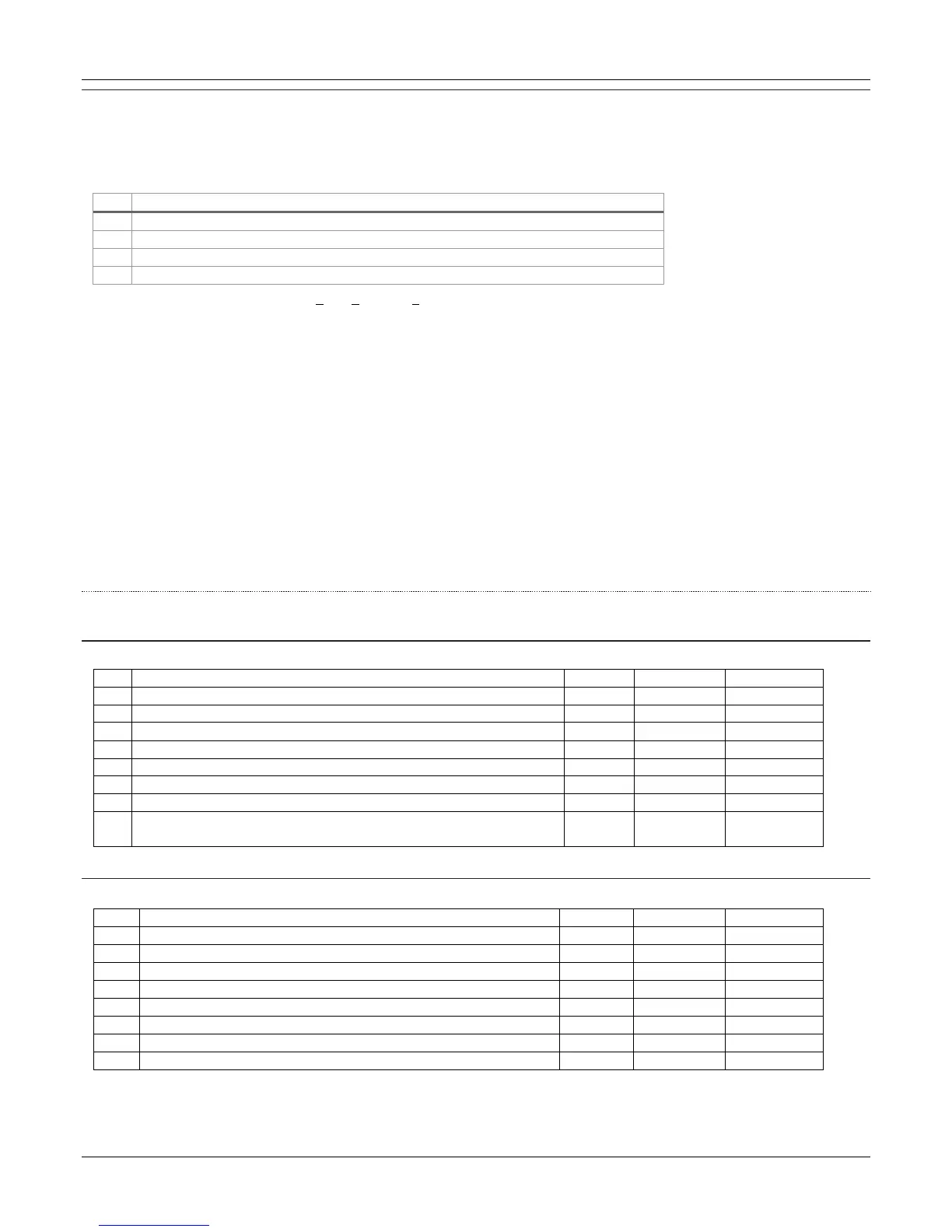
1 PRODUCT CONNECTION 8 FIELD WIRES REQUIRED (135046)
DIRECT PULSE OUTPUT BOARD WIRING
Wiring is to be connected directly to the Pulse Output Board.
OPTIONAL JUNCTION BOX WIRING
Wiring is to be connected to the terminal strip inside the optional junction box.
Continued on next page …