Bennett 3000 Spec 300 Series Instruction Manual Installation Instructions
27
1. Connect the Blue 14ga. wire to the 719 CPU Board at TS2 Terminal 2 or to the optional Junction Box at Terminal 3 as indicated in the
diagram. Connect the other end to the Submerged Pump Control Relay Box for Product A.
2. Connect the Brown 14ga. wire to the 719 CPU Board at TS2 Terminal 3 or to the optional Junction Box at Terminal 4 as indicated in
the diagram. Connect the other end to the Submerged Pump Control Relay Box for Product B.
3. Place 1 blue jumper between P1 to P3 on the 719 CPU and 1 brown jumper between P2 to P4 on the 719 CPU.
SUCTION PUMP MOTOR RELAY
A separate circuit and circuit breaker will be required for each pumping unit motor. Place the pumping unit motor power circuit breakers
on the opposite phase from the dispenser’s electronic power or on 240VAC. This will keep the dispenser’s electronic power free from
electronic noise. The dispenser may have one motor (single product) or two motors (dual product). Each motor requires two or three
field wires.
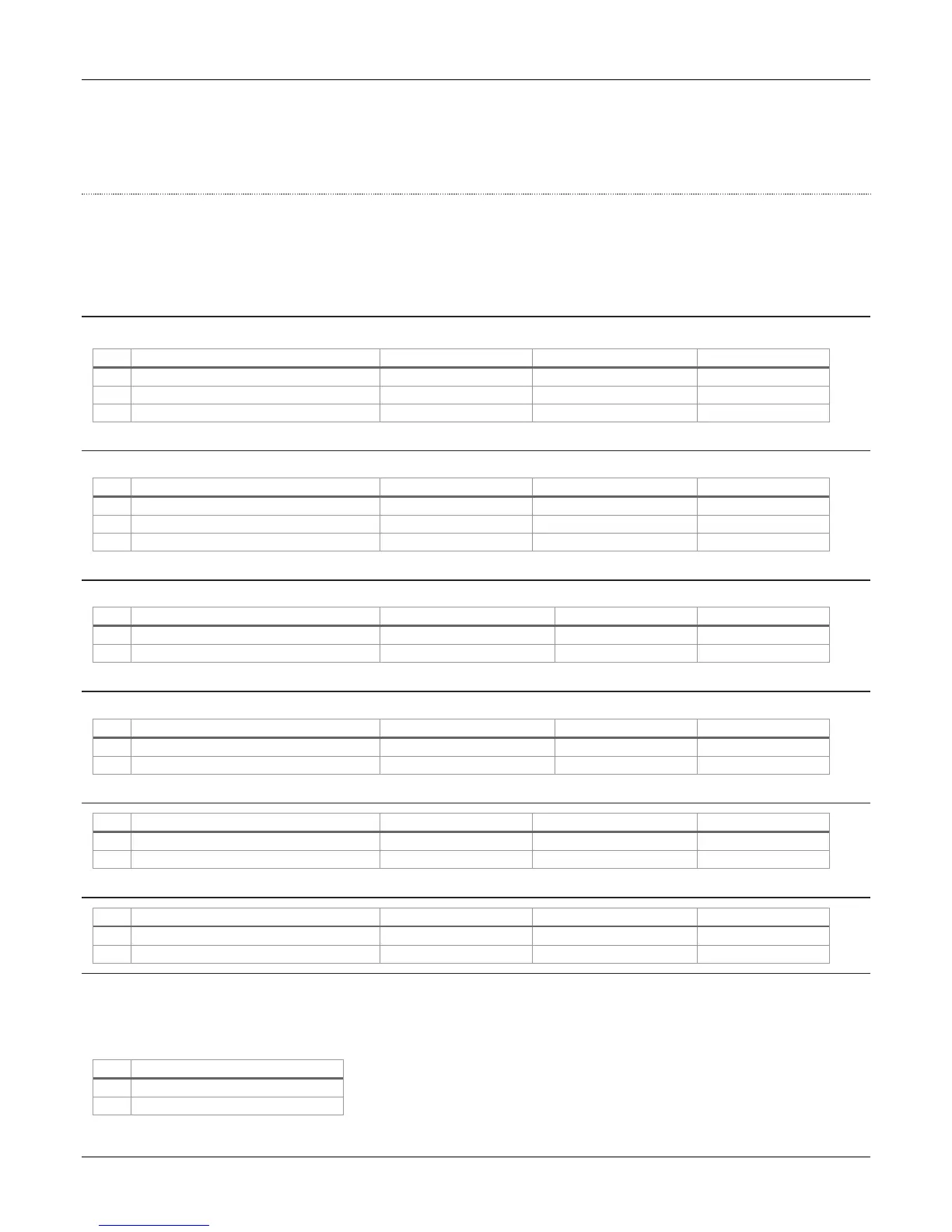
3-PHASE (380VAC) MOTOR A RELAY CONNECTION – PRODUCT A (135049)
Use a 15 AMP 3-phase circuit breaker (CB#2), which is supplied by the customer. Note: No more than 2 pumps per breaker.
Brown #14 – Product “A” Motor Control
Orange #14 – Product “A” Motor Control
Yellow #14 – Product “A” Motor Control
3-PHASE (380VAC) MOTOR B RELAY CONNECTION – PRODUCT B (135049)
Use a 15 AMP 3 phase circuit breaker (CB#2), which is supplied by the customer. Note: No more than 2 pumps per breaker.
Brown #14 – Product “B” Motor Control
Orange #14 – Product “B” Motor Control
Yellow #14 – Product “B” Motor Control
STANDARD SINGLE PHASE (120/240VAC) MOTOR A RELAY CONNECTION – PRODUCT A (135050)
Use a 15 AMP neutral breaking circuit breaker (CB#2), which is supplied by the customer. Note: No more than 2 pumps per breaker.
Blue #14 – Product “A” Motor Control
White #14 – Product “A” Motor Control
Circuit Breaker #2 – Neutral
STANDARD SINGLE-PHASE (120/240VAC) MOTOR B RELAY CONNECTION – PRODUCT B (135050)
Use a 15 AMP neutral breaking circuit breaker (CB#3), which is supplied by the customer. Note: No more than 2 pumps per breaker.
Red #14 – Product “B” Motor Control
White #14 – Product “B” Motor Control
Circuit Breaker #3 – Neutral
BIG FUELER SINGLE PHASE (240VAC) MOTOR A RELAY CONNECTION – PRODUCT A (135085)
Blue #14 – Product “A” Motor Control
White #14 – Product “A” Motor Control
BIG FUELER SINGLE-PHASE (240VAC) MOTOR B RELAY CONNECTION – PRODUCT B (135085)
Red #14 – Product “B” Motor Control
White #14 – Product “B” Motor Control
INTERCOM SYSTEMS (OPTIONAL)
Intercom wiring must be in a separate conduit from the dispenser conduit. DO NOT install intercom wiring in the same conduit as the
dispenser wiring or else the Bennett Warranty will be voided and improper system operation will result. If the dispenser is ordered with
an intercom (speaker and call button), the Installer must pull wires for it.
#18 Wire - Call Button (optional)