07/ 2018
BENNING ST 725
30
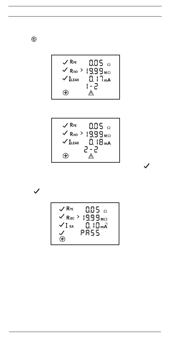
BENNING ST 725 in mains operating mode:
- The BENNING ST 725 interrupts the testing procedure after the R
ISO
(insulating resistance)
measurement and requests the user to switch the mains voltage of 230 V to the test socket
1
by showing a flashing "I
LEAK
" symbol. Make sure that the test sample is protected and
press the -key
4
to measure the protective conductor current by means of the differential
current measurement method.
- The protective conductor current measurement (differential current measurement method)
only starts as soon as the mains voltage is correct applied (see chapter 8.3).
step 1 of 2:
- After a measuring time of 5 seconds or by pressing the key
4
, mains polarity will be
reversed and the protective conductor current will be measured with reversed mains voltage
("L/N" - "N/L"). The highest measured value of both measurements will be displayed. (step 2
of 2)
step 2 of 2:
- If the protective conductor current is lower than the admissible limiting value, a will be
shown next to the I
LEAK
symbol.
- The overall test is considered to be passed, if "PASS" is shown on the display.
As an alternative:
BENNING ST 725 in battery operating mode (without mains supply):
- Similarly, a will be shown next to the I
EA
symbol, if the protective conductor current I
EA
(al-
ternative leakage current measurement method) is lower than the admissible limiting value.
- The test is considered to be passed, if "PASS" is shown on the display.
Seegure4: TestingofdevicesofprotectionclassI(deviceswithprotectiveconductorand
accessible conductive parts which are connected to the protective conductor)
Note on measuring the protective conductor resistance:
- Alternatively, the measurement of the protective conductor resistance R
PE
can be carried out
as permanent measurement (max. 2 x 90 seconds). For this purpose press the key
2
for
approx. > 5 seconds until the symbol appears on the display. Check the connecting line of
the test object by bending it over the entire length in order to detect weak points or a break of
the protective conductor. The BENNING ST 725 continuously records the current measured
value on the display and stores the maximum value in the memory. By pressing the key
2
again, the measurement is carried out with reversed polarity. Press the key
2
again to
indicate the maximum value of R
PE
on the display and to continue the testing procedure as
described in section 9.1.
Note on measuring the protective conductor current in mains operating mode:
- Alternatively, the measurement of the protective conductor current I
LEAK
can be carried
out as permanent measurement (max. 2 x 5 minutes). Press the key
4
for approx. > 5
seconds to start permanent measurement. After 5 minutes, the polarity of the mains voltage
will be reversed automatically ("L/N" - "N/L"). By pressing the key
4
earlier, the mains
voltage polarity reversal can be activated manually and by pressing the key
4
again, the