by AP2106A (ASIC scanner controller) and by a single-chip
microprocessor: W78E516B which is compatible with 8052. When
requested, these pixels data are transferred via SCSI output port to host
computer. To get the whole image data, the line motor steps forward to
next scan-line, and the same procedures are conducted for this scan-line.
A home sensor is used for the home positioning of the line-motor. If a
color image is requested, the color CCD is co-operated with every
scan-line.
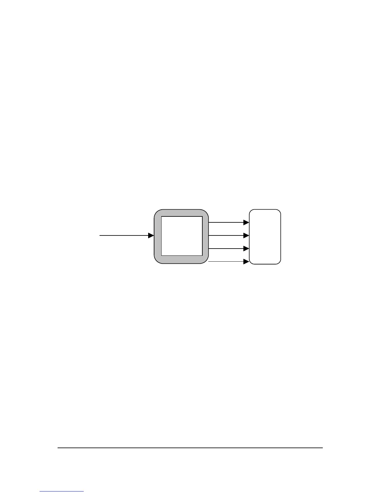
The Power board ( please refer to figure 2-3) transforms the AC voltage
into the required power sources. It has multiple DC outputs: +5V, +12V,
and +16V. It integrates a DC/AC inverter into this board, for converting
DC 12V to high-frequency (~30K) AC voltage (~400 V, Dangerous) for the
Lamp.
Main
Board
AC
100~240V
Power
Board
5V
12V
12V
16V
Figure 5-3 Film Scanner Power Board. Block
The 2740S scanner MainBoard is mainly composed of the analog circuits,
a AP2106A (ASIC scanner controller) , and a single-chip microprocessor
(W78E516). Please refer to figure 5-4
Electrical Systems API Confidential 5-3
No Copy/Reproduction allowed


 To Next Page