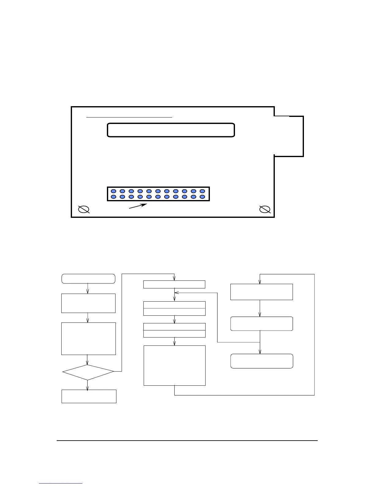
5.5.3 CCD/Home Sensor Board
There is one connector on the CCD board in 2740S scanner (referring to
figure 5-9), the connector description is as following.
2740S CCD PCB
J1
CCD
Figure 5-9
5.6 Main Flow Chart of Film Scanner
Start (power-on)
1. Initial system and CPU parameter
2. Reset components condition
3. Reset communication mode
System self test:
1. test ROM
2. test all RAM
3. check scanner motor and
position sensor
4. test CCD and lamp
5. test analog processor ICs
Check burn-in mode?
Yes
Burn-in test
Initial communication mode
Receiving host command and data
Send target message to host
"START SCAN" command
Calibration
Adjust scanning parameters:
1. brightness
2. contrast
3. shadow-highlight
4. gamma correction
5. multi bit and single bit
6. window mode
7. line art and halftone
8. scalling and resolution
9. matrix operation
Send scanned data
(* control scanning timing and
handshaking timing *)
End of scan
Next scan
Next scan
Stop (power-off)
Figure 5-10 Main Flow Chart of Film Scanner
5-10 API Confidential Electrical Systems
No Copy/Reproduction allowed
 Loading...