Doc No. 20-45-159 Page 58 of 60
7. Replacement Parts.
Note
It is recommended that only suitably competent persons are
allowed to undertake replacement of parts.
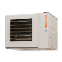
7.1 Burner.
• Disconnect electrical supply to the heater and shut o
gas supply.
• Disconnect gas supply
• Detach electrical connections via plugs.
R40 series:
• Using an 13mm spanner, remove the nut holding the
unit to the burner ange.
• Withdraw the burner from the throat of the heat
exchanger.
RL34/44 series:
• Using a 6mm Allen key, remove the bolt holding the
burner to the ange.
• Pull the burner forward on the two supporting bars.
Caution - Heavy!
• Remove the two supporting bar bolts and carefully
remove the burner through the throat of the ange.
• Replace in reverse order.
7.2 Controller
• Disconnect electrical supply to the heater.
• Remove the burner cover.
• Remove the screw xing the controller to the base
and withdraw controller.
• Replace in reverse order.
7.3 Electrode and Probe
• Disconnect electrical supply to the heater.
• Remove the burner cover.
R40 series:
• Using an 13mm spanner, remove the nut holding the
unit to the burner ange.
• Withdraw the burner from the throat of the heat
exchanger, support on bracket/ange lugs.
• Remove the xing screw(s) holding the End Cone and
withdraw from burner head.
• Loosen the screw clamping the electrodes.
RL34/44 series:
• Using a 6mm Allen key, remove the bolt holding the
burner to the ange.
• Pull the burner forward on the two supporting bars.
• Loosen the screw clamping the electrodes.
• Withdraw electrodes forward and away from the
burner.
• Replace in reverse order.
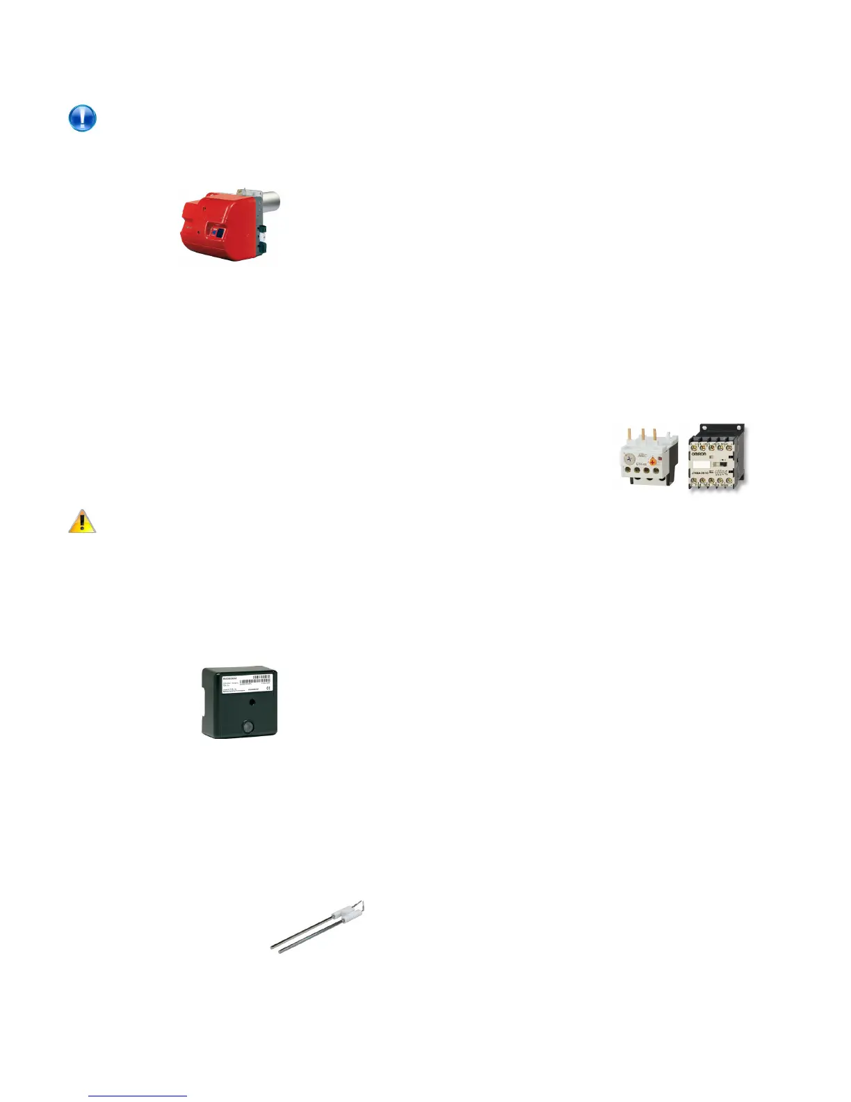
7.4 Contactor/Overload
• Disconnect electrical supply to the heater.
• Remove front panel (below burner)
The contactor and overload are located on the electrical panel
plate situated on the right hand side of the unit.
For Overload:
• Disconnect all wiring to the to the overload noting
which cables are connected to which terminals
• Loosen the three screws in contactor terminals 2, 4
and 6
• Pull the overload in a downwards movement and
unclip from the back of the contactor.
• Replace in reverse order.
For Contactor:
• Disconnect all wiring to the to the contactor and
overload noting which cables are connected to which
terminals
• Unscrew the two screws xing the contactor to the
electrical panel and remove.
• Loosen the three screws in contactor terminals 2, 4
and 6
• Pull the overload in a downwards movement and
unclip from the back of the contactor.
• Replace in reverse order.