INST-TS1-V13
18/11/10
Page 5
4. Mounting and Installation
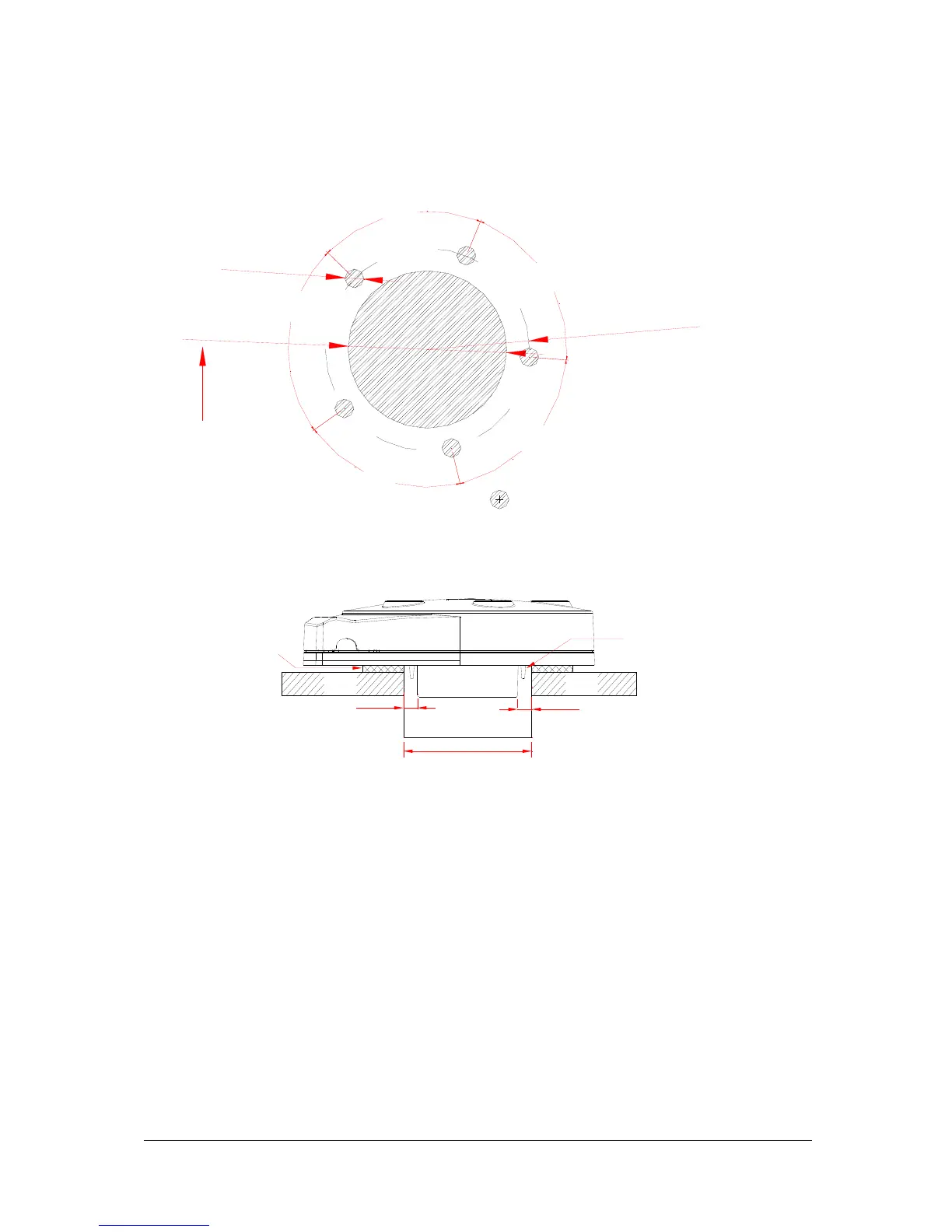
INDICATES CUTOUT
6
8
°
8
0
°
68°
7
2
°
7
2
°
R
2
7
[
R
1
1
/
1
6
"
]
VERY IMPORTANT:
DIAMETER MUST NOT BE
LESS THAN Ø42mm
Ø
4
2
[
Ø
1
5
/
8
"
]
Ø
5
[
Ø
3
/
1
6
"
]
42mm
4.5mm
4.5mm
ACOUSTIC
PROTRUSION
TANK
LID
TANK
LID
IMPORTANT
SIDE WALLS OF ACOUSTIC PROTRUSION MUST BE NO
CLOSER THAN 4.5mm TO THE TANK SIDES OF THE
CUTOUT HOLE
GASKET
GLUE
BARRIER
RING
The acoustic protrusion should be positioned in the tank aperture in the centre of the
hole. The protrusion should ideally be protruding into the tank and not be recessed in the
hole. See drawing above.
For tightening screws ensure base and washers are sitting flat. Tighten screw until screw
head makes contact with the washer, and then tighten another 2 full turns.
Maximum torque for the mounting screws is 0.5 Newton meter.
Note: Drawing is not to scale. Please use the tank gasket as a template and make sure
the tank hole is 42mm.