7
In particular on the boiler display:
- it is no longer possible to set the boiler OFF/WINTER/SUMMER status (it is
set by the OT+ remote control)
- it is no longer possible to set the domestic hot water setpoint (it is set by the
OT+ remote control)
- the combination of the A+B keys remains active for the setting of the DOME-
STIC HOT WATER COMFORT function
- the domestic hot water setpoint (I005) is displayed in the INFO menu
- the heating setpoint value calculated by the OT+ remote control (I017) is
displayed in the INFO menu
- the heating setpoint set on the boiler display is used only if there are heat
requests from the TA and the OT+ remote control does not have a request if
the parameter: 311 = 1 or 311 = 0,butthe VZONE jumper on the adjustment
board is closed. This value is displayed in the INFO menu (I016)
.
- to activate the “Combustion analysis” function with an OT+ remote control
connected,youmusttemporarilydisabletheconnectionbysettingthepa-
rameter 803 = 0 (SERVICE); remember to reset this parameter once the
functionhasnished.
Key 3 remains active for the visualisation of the INFO menu and the enabling
of the SETTINGS menu.
High voltage connections
The connection to the mains supply must be made via a separation device
with an omnipolar opening of at least 3.5 mm (EN 60335/1 - category 3). The
applianceworkswithalternatingcurrentat230Volt/50Hz,andisincompliance
with Standard EN 60335-1. It is obligatory to make the connection with a safe
ground/earth,incompliancewithcurrentdirectives.
b
The installer is responsible for ensuring the appliance is suitably earthed;
the manufacturer will not be liable for any damage resulting from an in-
correct or absent earth connection.
b
It is also advisable to respect the phase-neutral connection (L-N).
b
The earth conductor must be a couple of cm longer than the others.
b
To create the seal of the boiler use a clamp and tighten it on the cable
grommet used.
The boiler can operate with a phase-neutral or phase-phase power supply. It
is forbidden to use gas and/or water pipes to earth electrical appliances. Use
the power cable supplied to connect the boiler to the mains power supply. If the
powercablehastobereplaced,useaHARH05V2V2-F,3x0.75mm²cable,
Ø max external 7 mm.
2.5 Gas connection
The connection of the gas supply must be carried out in compliance with current
installationstandards.Beforecarryingouttheconnection,checkthatthetypeof
gas is that for which the appliance is set up
.
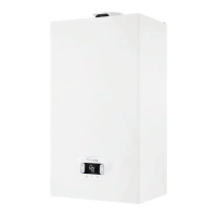
2.6 Removing the casing
Toaccessthecomponentsinside,removethecasingasshowninthegure.
b
Ifremovingthesidepanels,putthembackintheirinitialposition,referring
to the adhesive label on its wall
.
b
If the front panel is damaged it must be replaced
.
b
The noise absorbing panels inside the front and side walls ensure the
airtight seal for the air supply duct in the installation environment
.
b
It is therefore CRUCIAL after the dismantling operations to correctly re-
positionthecomponentstoensuretheboiler’ssealiseective
.
2.7 Flue gas exhaust and combustion air suction
Toevacuatethecombustionproducts,refertoUNI7129-7131.Alwayscomply
withlocalstandardsoftheFireDepartment,theGasCompanyandwithpossi-
ble municipal dispositions.
Itisessentialfortheevacuationoftheuegasesandtheadductionoftheboi-
ler’s combustion air that only original pipes be used (except C6) and that the
connectionismadecorrectlyasshownintheinstructionsprovidedwiththeue
gases accessories
.
Asingleuecanbeconnectedtoseveralappliancesprovidedthateveryap-
pliance is the condensing type.
b
b
“Straightlength”meansfreeofbends,andincludesterminalsandjoints.
b
Theboilerissuppliedwithouttheuegasexhaust/airsuctionkit,sinceit
ispossibletousetheaccessoriesforcondensingappliancesthatbestt
the installation characteristics (see catalogue
).
b
Themaximumlengthsofthepipesrefertotheueaccessoriesavailable
in the catalogue
.
b
Itiscompulsorytousespecicpipes
.
b
Thenoninsulateduegasoutletpipesarepotentialsourcesofdanger
.
b
The use of a longer pipe causes a loss of output of the boiler
.
b
The exhaust pipes can face in the direction most suited to the installation
requirements
.
b
Asenvisagedbycurrentlegislation,theboilerisdesignedtotakeinand
disposeofuegascondensateand/ormeteoricwatercondensatederi-
vingfromtheuegasdischargesystemusingitsownsiphon
.
b
If a condensate relaunch pump is installed, check the technical data
(providedbythemanufacturer)regardingoutput,toensureitoperates
correctly
.
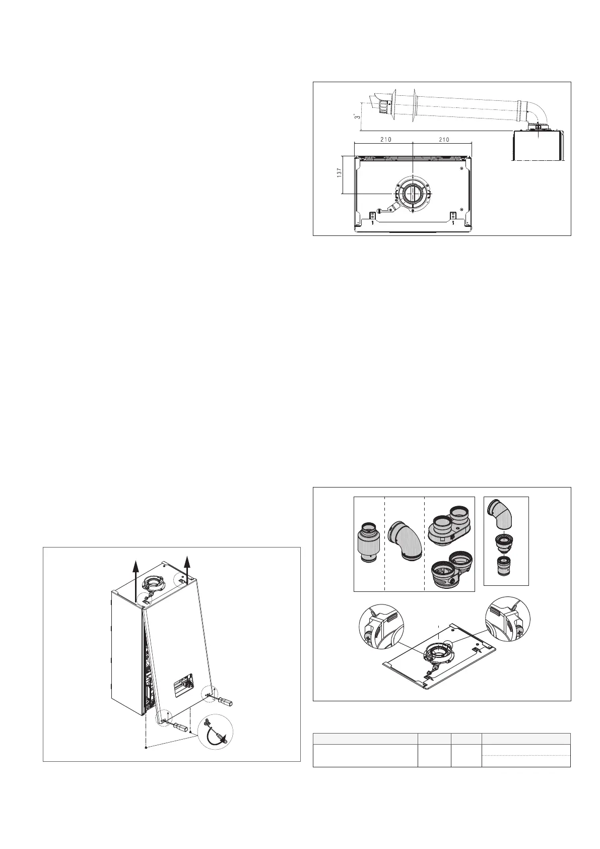
- Positionthedischargepipesothattheconnectionsitsfullyupagainsttheue
gases turret of the boiler.
- Afterpositioningit,makesurethe4notches(A) slip into the groove (B).
- Fully tighten the screws (C)thatholdthetwoangelockingterminals,sothe
bend itself is restrained held in place.
A
A
C
C
B
Ø80-125
B
B
B
B
B23P-B53P Ø60-100 Ø80-80
b
If the Ø 60-100 to Ø 80-80 splitter kit is used instead of the twin pipe
system,thereisalossinthemaximumlengthsasshowninthetable
.
Ø 50 Ø 60 Ø 80
Loss of length (m) 0,5 1,2
5,5foruegasespipe
7,5forairpipe
Twin pipes with Ø 80 pipework (Ø50 - Ø60 - Ø80)
Thankstotheboilercharacteristics,aØ80uegasexhaustpipecanbecon-
nected to the Ø50 - Ø60 - Ø80 piping ranges.

 Loading...