9
- Connect a pipe to the system discharge tap
(C),
then manually turn it coun-
terclockwisetoletthewaterowout
.
- Oncetheoperationshavebeencompleted,removethepipefromthesystem
discharge tap
(C)
and close it again
.
2.10 Emptying the domestic hot water circuit
Wheneverthereisriskoffrost,thedomestichotwatersystemmustbeemptied
in the following way:
- turno the main water supply tap
- turn on all the hot and cold
- drain the lowest points.
3 COMMISSIONING
3.1 Preliminary checks
First ignition is carried out by competent personnel from an authorised Technical
AssistanceCentre.Beforestartinguptheboiler,check:
t
hatthedataofthesupplynetworks(electricity,water,gas)correspondtothe
label data
thattheextractionpipesoftheuegasesandtheairsuctionpipesarewor-
king correctly
that conditions for regular maintenance are guaranteed if the boiler is placed
inside or between items of furniture
the seal of the fuel adduction system
thatthefuelowratecorrespondstovaluesrequiredbytheboiler
thatthefuelsupplysystemissizedtoprovidethecorrectowratetothe
boiler,andthatithasallthesafetyandcontroldevicesrequiredbycurrent
regulations
thatthecirculator rotates freely because, especially after long periodsof
inactivity,depositsand/ordebriscanpreventfreerotation
(
see paragraph
“7.4 Unlock of the circulator”).
3.2 First commessioning
Onrstignitionafterprolongedinactivityandaftermaintenance,beforeputting
theapplianceintooperationitisessentialtollthecondensatecollectionsiphon
bypouringabout1litreofwaterintotheboilercombustionanalysistake-oand
check
:
-
oatingofthesafetyshutter
-
thecorrectowofwaterfromtheboileroutletdischargepipe
-
the leaktightness of the condensate drain connection line
.
Correct operation of the condensate drain circuit (siphon and pipes) requires
thatthecondensateleveldoesnotexceedthemaximumlevel(max).Priorl-
ling of the siphon and the presence of the safety shutter inside the siphon is
designed to prevent the escape of combustion gases into the environment
.
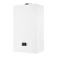
3.3 Venting cycle
Position the system’s master switch to the “on” position.
Everytimetheboilerispowered,a4-minuteventingcycleisrun.Thedi-
splay shows .
Tointerrupttheventingcycle,press the key shown in the figure below.
bar
rpm
°
C
1
888
.
o
o
o
b
Whentheventingcycleisrunning,allheatrequestsareinhibited
apart from DHW unless the boiler is OFF.
The venting cycle can also be interrupted (if the boiler is not OFF) by a
DHW request.
3.4 Setting the thermoregulation
Thethermoregulationisonlyavailableifanexternalprobeisconnected,andis
only active for the HEATING function.
THERMOREGULATION is enabled in the following way:
set parameter 418 =1.
With 418 = 0ortheexternalprobedisconnected,theboilerworks with a fixed
point. The temperature value measured by the external probe is visualised in
“4.3 INFO menu ” under item I009.
The thermoregulation algorithm will not use the measured external tempera-
turevaluedirectly,butratheracalculatedexternaltemperaturethattakesinto
accountthebuilding’sinsulation:inbuildingsthatarewellinsulated,theoutdoor
temperature variations will have less impact than those that are poorly insulated
by comparison.
This value can be viewed in the INFO menu under item I010
REQUEST FROM OT CHRONOTHERMOSTAT
Inthiscase,thedeliverysetpointiscalculatedbychronohermostatonthebasis
of the external temperature value and the difference between the real ambient
temperature and the required ambient temperature.
REQUEST FROM ROOM THERMOSTAT
Inthiscase,thedeliverysetpointiscalculatedbytheadjustmentboardonthe
basisoftheexternaltemperaturevalue,toobtainanestimatedambienttempe-
rature value of 20° (reference ambient temperature).
There are 2 parameters that compete to calculate the output setpoint:
slope of the compensation curve (KT) - editable by technical staff
offset on the reference ambient temperature - editable by the user.
TYPE OF BUILDING (parameter 432)
It is indicative of the frequency with which the value of the calculated outdoor
temperatureforthermoregulationisupdated,alowvalueforthisvaluewillbe
used for buildings that have little insulation.
SEXT REACTIVITY (parameter 433)
It is an indication of the speed with which variations of the measured outdoor
temperature affect the calculated outdoor temperature value for thermoregula-
tion,lowvaluesindicatehighspeeds.
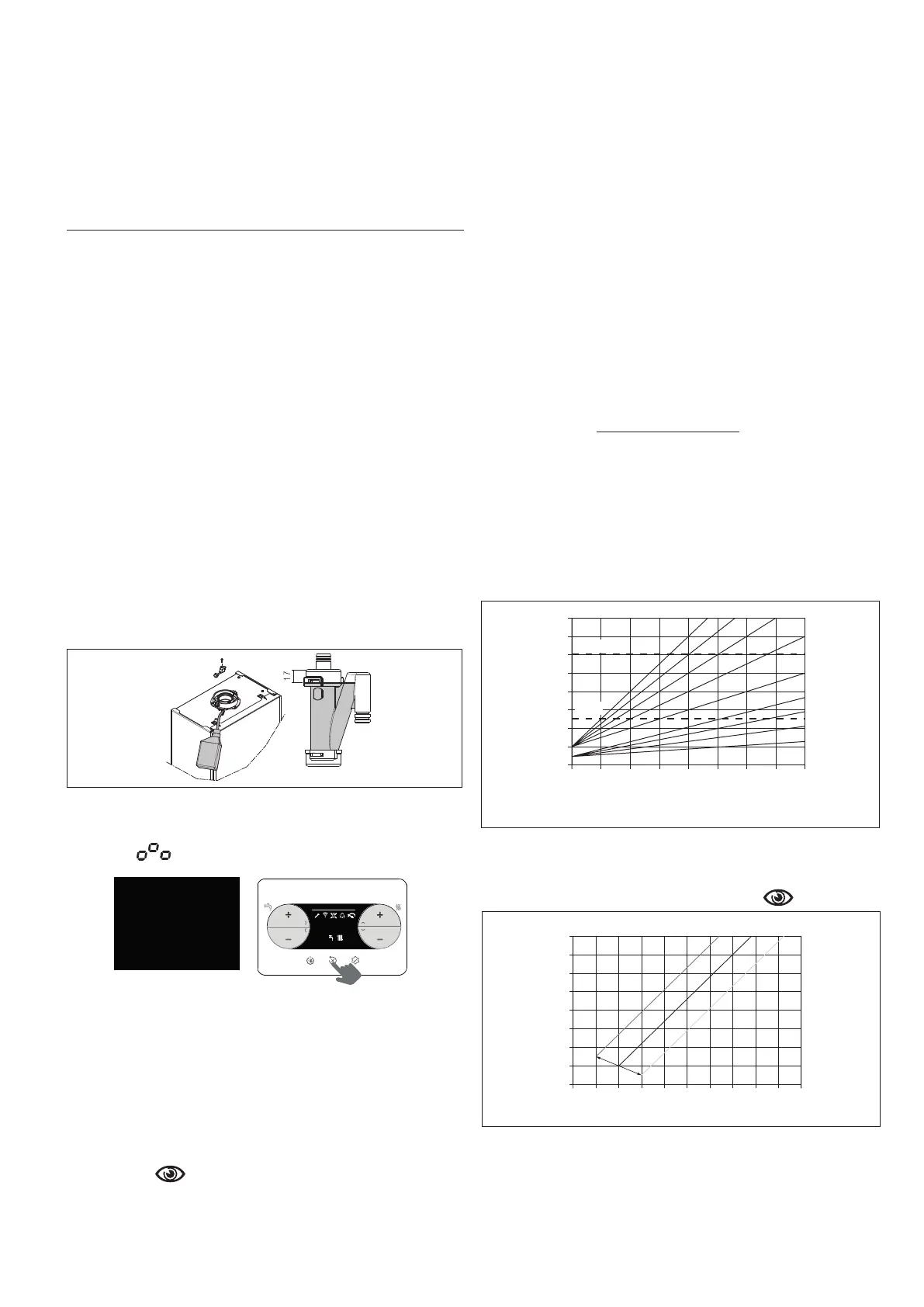
Choice of the thermoregulation curve (parameter
419
)
The thermoregulation curve for heating maintains a theoretical temperature of
20°Cindoors,whentheoutdoortemperatureisbetween+20°Cand-20°C.The
choice of the curve depends on the minimum outdoor temperature envisaged
(and therefore on the geographical location) and on the delivery temperature
envisaged (and therefore on the type of system). It is carefully calculated by the
installer on the basis of the following formula:
KT = delivery T envisaged - Tshift
20- min. design external T
Tshift = 30°C standard system
25°C floor system
Ifthecalculationproducesanintermediatevaluebetweentwocurves,youare
advised to choose the thermoregulation curve closest to the value obtained.
Example
:
ifthevalueobtainedfromthecalculationis1.3,thisisbetweencurve
1andcurve1.5.Choosethenearestcurve,i.e.1.5.ThesettableKTvaluesare
as follows:
standardsystem:1.0÷3.0
floorsystem0.2÷0.8.
Parameter 419 can be used to set the required thermoregulation curve:
T HT maximum heating setpoint temperature (standard systems)
maximum heating setpoint temperature (free-standing systems)
3,0
100
90
80
70
60
50
40
30
20
20
Temperatura di mandata (°C)
Temperatura esterna (°C)
15 10 50-5 -10 -15 -20
2,5 2,0
1,5
T AT
1,0
0,8
0,6
0,4
0,2
T BT
CURVE DI TERMOREGOLAZIONE
delivery temperature (°C)
external temperature (°C)
T HT
T LT
Offset on the reference ambient temperature
Inanycase,theusercanindirectlymodifytheHEATINGsetpointvaluebydefi-
ning,forthereferencetemperature(20°C),anoffsetthatcanvarywithintheran-
ge-5to+5(offset0=20°C).Forthecorrectionoftheoffset,refertoparagraph
“6.3 Setting the heating setpoint with an external probe ”.
90
80
70
60
50
40
30
20
10
30
Temperatura di mandata (°C)
Temperatura esterna (°C)
25 20 15
+5°C
0°C
-5°C
10 50-5 -10 -15
-20
CORREZIONE CURVA CLIMATICA
CLIMATIC CURVE CORRECTION
delivery temperature (°C)
external temperature (°C)
NIGHT-TIME COMPENSATION (parameter 420)
IfatimerisconnectedtotheAMBIENTTHERMOSTATinput,parameter420
can be used to enable night-time compensation.
Set parameter 420 = 1
Inthiscase,whentheCONTACTisCLOSED,theheatrequestismadebythe
flowsensor,onthebasisoftheoutdoortemperature,toobtainanominalam-
bient temperature on DAY level (20 °C). The OPENING OF THE CONTACT
doesnotproduceaswitch-off,butareduction(paralleltranslation)oftheclimatic
curve on NIGHT level (16 °C).

 Loading...