8
b
Forthepipe,youareadvisedtomakeaprojectcalculationinorderto
respect the relevant regulations in force.
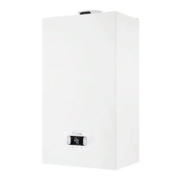
Thetableshowsthestandardcongurationsallowed
.
Air suction
1 bend 90° Ø 80
4.5m pipe Ø80
Flue gas
discharge
1 bend 90° Ø 80
4.5m pipe Ø80
Reduction from Ø80 to Ø50 from Ø80 to Ø60
Fluebasebend90°,Ø50orØ60orØ80
For ducting pipe lengths see table
The boilers are factory set to:
CH rpm DHW rpm Max length pipes (m)
Ø50 Ø60 Ø80
model A
7.000 8.700
6 19 95
1 9 45
model B
7.000 8.700 4 16 80
7.400 8.700 0 7 35
Shouldgreaterlengthsberequired,compensatethepressuredropwithanin-
creaseinther.p.m.ofthefan,asshownintheadjustmentstable,toprovidethe
rated heat input,referring to paragraph
“3.9 Adjustments”
.
b
Theminimumcalibrationshouldnotbemodied.
b
Incaseofnewfanspeedadjustment,carryouttheCO2 check procedu-
re as indicated in paragraph “3.8 Combustion analysis”.
Adjustment tables INSIDE CHIMNEY PIPES
twin ue pipe
Fan rotations rpm Pipes Ø50 Pipes Ø60 Pipes Ø80 ∆P at boiler outlet
CH DHW Maximum length (m)
model A
7.000 8.700 6 19 95 180
7.100 8.800 12 * 33 * 165 * 260
7.200 8.900 16 * 39 * 195 * 300
7.300 9.000 19 * 46 * 230 * 342
7.400 9.100 23 * 53 * 265 * 383
7.500 9.200 27 * 61 * 305 * 431
7.600 9.300 29 * 67 * 335 * 465
7.700 9.400 32 * 73 * 365 * 500
model B
7.000 8.700 4 16 80 180
7.100 8.800 8 * 26 * 130 * 260
7.200 8.900 11 * 32 * 160 * 300
7.300 9.000 14 * 38 * 190 * 342
7.400 9.100 17 * 44 * 220 * 383
7.500 9.200 19 * 50 * 250 * 431
7.600 9.300 22 * 56 * 280 * 465
7.700 9.400 25 * 62 * 310 * 500
(*) Maximum length that can be installed ONLY with class H1 discharge pipes.
compact twin ue pipe
Fan rotations rpm Pipes Ø50 Pipes Ø60 Pipes Ø80 ∆P at boiler outlet
CH DHW Maximum length (m)
model A
7.000 8.700
1
9 45 180
7.100 8.800
7 *
23 *
115
* 260
7.200 8.900
11 *
29 *
145
* 300
7.300
9.000 14 *
36 *
180
* 342
7.400
9.100 18 *
43 *
215
* 383
7.500
9.200 22 *
51 *
255
* 431
7.600
9.300 24 *
57 *
285
* 465
7.700
9.400 27 *
63 *
315
* 500
model B
7.400 8.700 0 7 35 190
7.500
8.800
4 *
17 *
85
* 256
7.600
8.900
7 *
23 *
115
* 300
7.700
9.000
10 *
29 *
145
* 340
7.800
9.100
13 *
35 *
175
* 380
7.900
9.200
15 *
41 *
205
* 417
8.000
9.300
18 *
47 *
235
* 458
8.100
9.400
21 *
53
* 265
* 500
(*) Maximum length that can be installed ONLY with class H1 discharge pipes.
TheØ50orØ60orØ80congurationscontainLabtestdata.Intheeventof
installationsthatdierfromtheindicationsinthe“standardcongurations”and
“adjustments”tables,refertotheequivalentlinearlengthsbelow.
b
Inanycase,themaximumlengthsdeclaredinthebookletareguarante-
ed,anditisessentialnottoexceedthem.
COMPONENT Linear equivalent in metres Ø80 (m)
Ø 50 Ø 60
Bend 45° 12,3 5
Bend 90° 19,6 8
Extension 0.5m 6,1 2,5
Extension 1.0m 13,5 5,5
Extension 2.0m 29,5 12
chimney for ducting
ø 50 mm or ø 60
mm or ø 80 mm
length
90° bend ø 50
mm ø 60 mm
or ø 80 mm
80-60 mm or
ø 80-50 mm
reduction
90° bends ø 80 mm
4,5m Ø 80mm
4,5m Ø 80mm
°
C
508
.
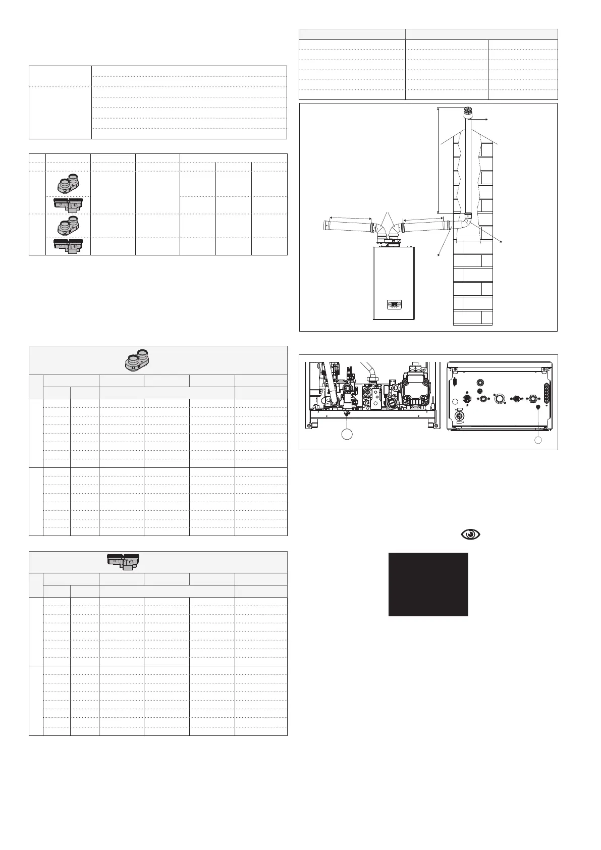
2.8 Filling the heating system and eliminating air
C
A
NOTE: llthesystemviathellingtap(A) making sure the boiler is electrically
powered.
NOTE:eachtimetheboilerispoweredup,theautomaticventingcycleiscar-
ried out.
NOTE: the presence of a water alarm (A40,A41orA42) does not allow the
venting cycle to be carried out.
Fill the heating system as follows:
- openthellingtap(A) turning it counterclockwise
- then access the Info menu (
“4.3 INF
O menu ”,itemI018),tocheck
that the pressure value reaches 1-1.5 bar
.1
5
.
NOTE: ifthemainspressureislessthan1bar,keepthellingtap(A) open
during the venting cycle. Close it when the cycle has ended.
To start the venting cycle:
- switchotheelectricalsupplyforafewseconds
- connectthepoweragain,leavingtheboilerOFF
- check that the gas tap is closed.
At the endofthecycle,ifthecircuitpressurehasdropped,openthellingtap
(A) again to bring the pressure back up to the recommended value (1-1.5 bar).
The boiler is ready after the vent cycle.
- Remove any air in the domestic system (radiators, zone manifolds, etc.)
using the bleed valves.
- Once again check that the system pressure is correct (ideally 1-1.5 bar) and
restore the levels if necessary.
- Ifairisnoticedwhenoperating,repeattheventcycle.
- Oncetheoperationsarenished,openthegastapandignitetheboiler.
At this point it is possible to carry out any heat request.
2.9 Draining the heating system
Beforedraining,settheboilertoOFFandshutotheelectricalsupplysetting
thesystem’smainswitchto“o”
.
- Close the heating system’s taps (if present
).

 Loading...