23
ENGLISH
CONTENTS
7
WARNING
This booklet contains data and information for both the user
and the installer.
In particular, the user should pay attention to the chapters:
- Warnings and safety
- Putting into service
- Maintenance.
a
The user must not carry out work on the safety devices, re-
place parts of the product, tamper with or attempt to repair the
appliance.
These operations must be entrusted exclusively
professionallyqualiedpersonnel.
b
The manufacturer is not liable for any damage caused by the
non-compliance with the above and/or the failure to comply
with the regulations.
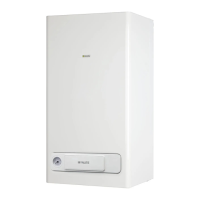
IDRABAGNO Lx 11 - 13
ENGLISH
These symbols are used in some parts of the manual:
7
Section destined for user also.
b
CAUTION! =
Identiesactions thatrequirecaution andade-
quate preparation.
a
STOP! =
IdentiesactionsthatyouMUSTNOTdo.
1 WARNINGS AND SAFETY
7
. . . . . . . . . . . . . . .24
2 DESCRIPTION OF THE APPLIANCE . . . . . . . . . . .25
2.1 Functional elements of the appliance / Max. dimensions and
connections . . . . . . . . . . . . . . . . . . . . . . . . . . . . . . . . . . . . . . 25
2.1.1 Models for indoor installation . . . . . . . . . . . . . . . . . . . . . . . . . 25
2.1.2 Models for outdoor installation . . . . . . . . . . . . . . . . . . . . . . . . 26
2.2 Water circuit . . . . . . . . . . . . . . . . . . . . . . . . . . . . . . . . . . . . . . 27
2.3 Multi-row wiring diagram . . . . . . . . . . . . . . . . . . . . . . . . . . . . 27
3 INSTALLATION . . . . . . . . . . . . . . . . . . . . . . . . . . . . . 28
3.1 Standards . . . . . . . . . . . . . . . . . . . . . . . . . . . . . . . . . . . . . . . . 28
3.2 Positioning . . . . . . . . . . . . . . . . . . . . . . . . . . . . . . . . . . . . . . . 28
3.3 Wall mounting. . . . . . . . . . . . . . . . . . . . . . . . . . . . . . . . . . . . . 28
3.3.1 Models for indoor installation . . . . . . . . . . . . . . . . . . . . . . . . . 28
3.3.2 Models for outdoor installation . . . . . . . . . . . . . . . . . . . . . . . . 29
3.4 Evacuating products of combustion . . . . . . . . . . . . . . . . . . . . 30
3.4.1 Models for indoor installation . . . . . . . . . . . . . . . . . . . . . . . . . 30
3.4.2 Models for outdoor installation . . . . . . . . . . . . . . . . . . . . . . . . 31
3.5 Electrical connections. . . . . . . . . . . . . . . . . . . . . . . . . . . . . . . 32
3.6 Gas connections. . . . . . . . . . . . . . . . . . . . . . . . . . . . . . . . . . . 32
3.7 Water connection . . . . . . . . . . . . . . . . . . . . . . . . . . . . . . . . . . 32
3.8 Anti-freezesystem(Modelsforoutdoorinstallation) . . . . . . . 32
3.9 Emptying the water heater . . . . . . . . . . . . . . . . . . . . . . . . . . . 32
3.10 Gas conversion . . . . . . . . . . . . . . . . . . . . . . . . . . . . . . . . . . . 32
3.11 Adjustments . . . . . . . . . . . . . . . . . . . . . . . . . . . . . . . . . . . . . . 33
4 PUTTING INTO SERVICE
7
. . . . . . . . . . . . . . . . 35
4.1 Controls interface . . . . . . . . . . . . . . . . . . . . . . . . . . . . . . . . . . 35
4.2 Description of icons . . . . . . . . . . . . . . . . . . . . . . . . . . . . . . . . 35
4.3 Selecting functions . . . . . . . . . . . . . . . . . . . . . . . . . . . . . . . . . 35
4.4 Start-up. . . . . . . . . . . . . . . . . . . . . . . . . . . . . . . . . . . . . . . . . . 36
4.5 Operating faults and reset . . . . . . . . . . . . . . . . . . . . . . . . . . . 37
4.6 Temporary shutdown . . . . . . . . . . . . . . . . . . . . . . . . . . . . . . . 37
4.7 Preparing for extended periods of disuse . . . . . . . . . . . . . . . 37
4.8 Parameters menu. . . . . . . . . . . . . . . . . . . . . . . . . . . . . . . . . . 38
4.8.1 Table of parameters . . . . . . . . . . . . . . . . . . . . . . . . . . . . . . . . 38
4.8.2 Reset to factory settings. . . . . . . . . . . . . . . . . . . . . . . . . . . . . 38
5 MAINTENANCE
7
. . . . . . . . . . . . . . . . . . . . . . . . 39
6 REMOVING THE CASING . . . . . . . . . . . . . . . . . . . . 39
6.1 Models for indoor installation . . . . . . . . . . . . . . . . . . . . . . . . . 39
6.2 Models for outdoor installation . . . . . . . . . . . . . . . . . . . . . . . . 39
6.3 Accessing the modulation circuit board . . . . . . . . . . . . . . . . . 40
7 TROUBLESHOOTING. . . . . . . . . . . . . . . . . . . . . . . .41
8 TECHNICAL SPECIFICATIONS . . . . . . . . . . . . . . . . 42
 Loading...
