Installation 4
REPLACING AN OLD PUMP
Hazardous voltage. Disconnect power to
pump before working on pump or motor.
Step 1. Drain and remove the old pump. Check the old
pipe for scale, lime, rust, etc., and replace it if
necessary.
Step 2. Install the pump in the system. Make sure that all
pipe joints in the suction pipe are air-tight as well
as water tight.
If the suction pipe can suck air, the
pump will not be able to pull water from the well.
Step 3. Adjust the pump mounting height so that the
plumbing connections do not put a strain on the
pump body. Support the pipe so that the pump
body does not take the weight of piping or fittings.
You have just completed the well plumbing for
your new shallow well jet pump. Please go to
Page 6 for discharge pipe and tank connections.
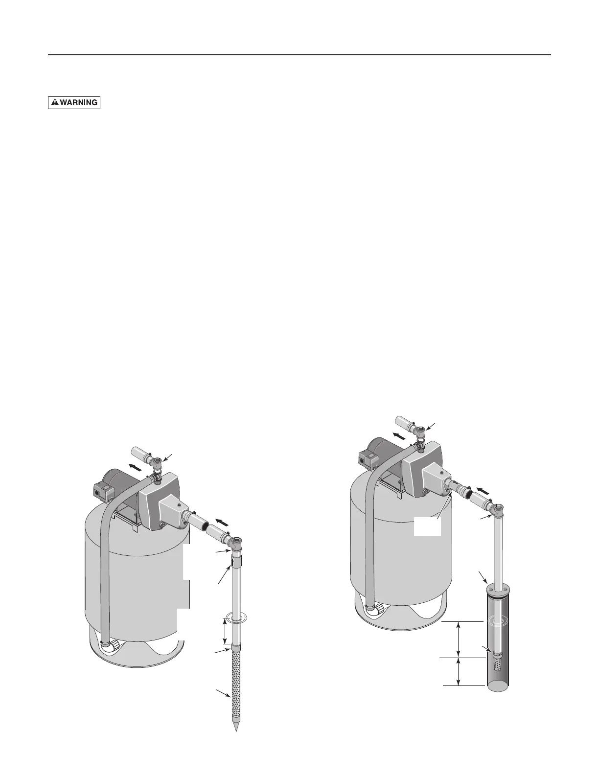
WELL POINT (DRIVEN POINT)
INSTALLATION (Figure 1)
Step 1. Drive the well, using “drive couplings” and a
“drive cap”. “Drive fittings” are threaded all the
way through and allow the pipe ends to butt
against each other so that the driving force of the
maul is carried by the pipe and
not
by the
threads. The ordinary fittings found in hardware
stores are not threaded all the way through the
fitting and can collapse under impact. “Drive fit-
tings” are also smoother than standard plumbing
fittings, making ground penetration easier.
Step 2. Mount the pump as close to the well as possible.
Step 3. Use the fewest possible fittings (especially
elbows) when connecting the pipe from the well
point to the pump suction port. The suction pipe
should be at least as large as the suction port on
the pump (include a check valve if your pump is
not equipped with one – see Figure 1). Support
the pipe so that there are no dips or sags in the
pipe, so it doesn’t strain the pump body, and so
that it slopes slightly upward from the well to the
pump (high spots can cause air pockets which
can air lock the pump). Seal the suction pipe
joints with teflon tape or a teflon based pipe joint
compound. Joints must be air- and water-tight.
If
the suction pipe can suck air, the pump cannot
pull water from the well.
If one well point does
not supply enough water, consider connecting
two or three well points to one suction pipe.
You have just completed the suction piping for
your new shallow well jet pump. Please go to
Page 6 for discharge pipe and tank connections.
CASED WELL INSTALLATION, 2” OR
LARGER CASING (Figure 2)
Step 1. Mount the pump as close to the well as possible.
Step 2. Assemble the foot valve, strainer, and well pipe
(see Figure 2). Make sure that the foot valve
works freely.
Min.