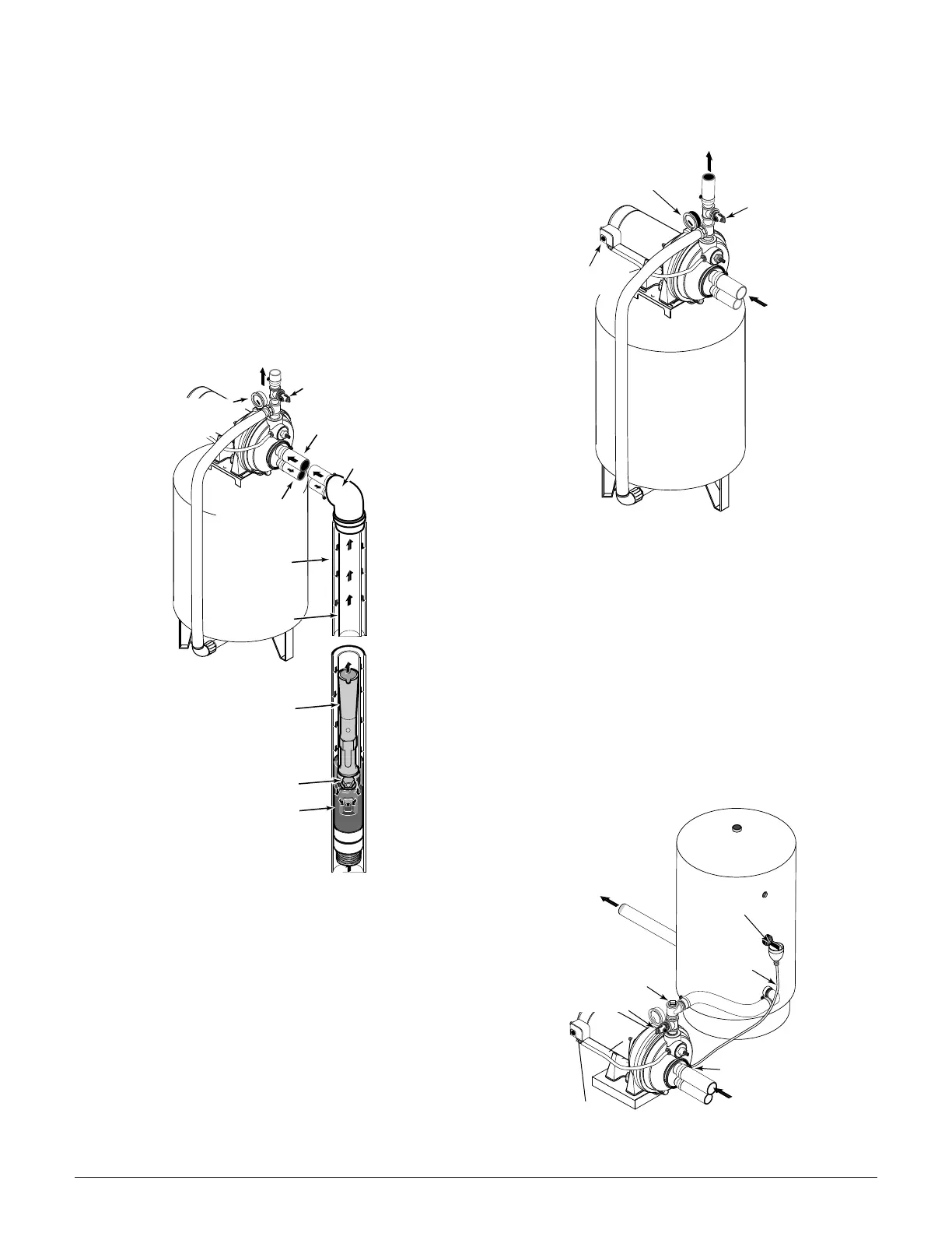
New Deep Well 2” Well (Figure 9)
1. Mount the pump as close to the well as possible.
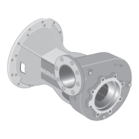
2. Assemble Berkeley ejector kit BK4840 (sold separately),
well piping, and well head adapter according to the
instructions provided with the ejector package (See
Figure 9.) Use galvanized drop pipe with turned cou-
plings to allow proper flow. Follow the instructions includ-
ed with the kit in order to match the nozzle and venturi to
your well conditions.
3. Run two pipes (one smaller drive pipe, one larger suction
pipe) from the well to the pump. Support the pipe so that
there are no dips or sags in the pipe, so it doesn’t strain
the pump body, and so that it slopes slightly upward from
the well to the pump (high spots can cause air pockets
which can air lock the pump). Seal the suction pipe joints
with teflon tape or a teflon-based pipe joint compound.
Joints must be air and water-tight. If the suction pipe can
suck air, the pump cannot pull water from the well.
Discharge Pipe and Pressure Tank
Connections
PRE-CHARGE TANK CONNECTION (FIGURE 10)
1. Install a close nipple and a tee in the pump discharge
port (See Figure 10). The pipe size must be at least as
large as the discharge port. Run a pipe or reinforced
hose from one arm of the tee to the port on the pre-
charged tank.
2. Install a second close nipple and tee with a relief valve in
the tee.
3. Connect the other end of the second discharge tee to
your plumbing system.
4. Check the pre-charge of air in the tank with an ordinary
tire gauge. The pre-charge should be 2 psi less than the
cut-in setting of the pump’s pressure switch. The pre-
charge is measured when there is no water pressure in
the tank. Your new pump has a 30/50 psi switch, so
adjust the tank pre-charge pressure to 28 psi.
STANDARD TANK CONNECTION (FIGURE 11)
1. Install a close nipple and a tee in the pump discharge
port. Mount a relief valve in one arm of the tee.
2. Install a second close nipple and tee in the open arm of
the first tee. Put a priming plug in one arm of the second
tee.
3. Run a pipe from the open arm of the second tee to the
inlet port of your tank. The pipe size must be at least as
large as the pump discharge port.
4. Remove the 1/8” NPT pipe plug from the pump Air
Volume Control (AVC) port (See Figure 11). Run tubing
from the pump’s AVC port to the port on the AVC mount-
ed on the tank. See instructions provided with tank and
AVC for details.
7