BERNINA International AG · Seestrasse 161 · CH-8266 Steckborn · Switzerland 9
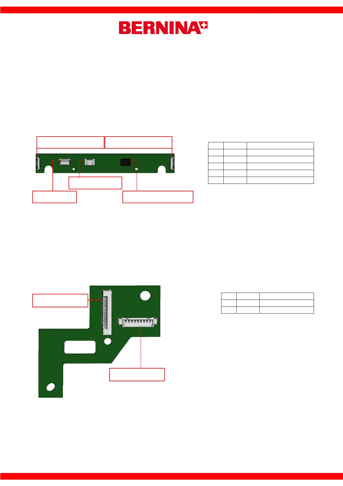
PCBA-Y-Arm
Consists of:
• 5 Cable connections
Connections:
As shown
Function:
• This circuit board functions primarily as an input/output board.
• The stepping motor and encoder for the stepping motor position are controlled over this board.
• An interrupter sensor (Y-Initializing) is also located on this board. When the mechanical rib on the Y-
Arm passes through this interrupter element, the signal will be recognized, which in turn means that
the Y-Arm is now in the programmed starting position.
PCBA-X-Carriage Rear
Consists of:
• A connection from/too the PCBA-Y-Arm
• A connection from/too the PCBA -Main-EMB
Connections:
As shown
Function:
• PCBA-X-Carriage transmits signals to and from the PCBA-Y-Arm and PCBA-EMB-Main.
No. Colour Target
P-1 white PCBA-X-Carriage Front
P-2 white PCBA-X-Carriage Rear
P-3 white Encoder-Y-Axis
P-4 white PCBA-Frame
P-5 black Stepping Motor Y-Axis
No. Colour Target
P-1 white PCBA-PCBA-Main
P-2 white PCBA-Y-Arm
P-1
P-2
P-3
P-4
P-5
P-1
PCBA-X-Carriage rear
PCBA-Frame Stepping motor Y-Axis
Encoder-Y-Axis
PCBA-X-Carriage
P-1
P-2
PCBA-Y-Arm
PCBA-Main EMB
 Loading...