EasyManua.ls Logo

Bestop TrekStep Side-Mount User Manual

Bestop TrekStep Side-Mount
8 pages
To Next Page IconTo Next Page
Page #1 background imageLoading...
Page #1 background image
Installation Instructions
INSTALLATION TIME
SKILL LEVEL
1/2 Hour
1 - Easy
TOOLS
Vehicle Application
18 mm,
13 mm, 3/8"
8 mm, 3/16"
www.bestop.com - We’re here to help! Visit our web site and click on “Ask a Question”. Click here for more Truck Accessories by Bestop.
TrekStep Side–Mount™
Dodge 1500 Passenger Side
Fits 6.4' and 8' Beds
2002 – 2008
Part Number: 75408-15
Dodge 1500 Driver Side
Fits 6.4' and 8' Beds
2002 – 2008
Part Number: 75407-15
Dodge 2500/3500 Passenger Side
Fits 6.4' and 8' Beds
2002 – Current
Part Number: 75408-15
Dodge 2500/3500 Driver Side
Fits 6.4' and 8' Beds
2002 – Current
Part Number: 75407-15
13 mm
Note: Passenger side installation shown. Driver’s side uses the same steps to install.
Question and Answer IconNeed help?

Do you have a question about the Bestop TrekStep Side-Mount and is the answer not in the manual?

Bestop TrekStep Side-Mount Specifications

General IconGeneral
BrandBestop
ModelTrekStep Side-Mount
CategoryAutomobile Accessories
LanguageEnglish

Summary

Vehicle Application

Parts List and Hardware Identification

Step-by-Step Installation Guide

Locate Bed Support Rib

Identify the correct support rib under the truck bed and remove the frame bolt.

Install Frame Mount

Align the Frame Mount with the threaded hole and reinstall the frame bolt.

Assemble Cross Bar Mount

Thread nuts onto the M10-1.5 x 45mm Hex Head Screw for the Cross Bar Mount.

Secure Frame Mount Foot to Frame Mount

Attach the Frame Mount Foot to the Frame Mount using specified bolts and nuts.

Install Top Bracket

Insert the Top Bracket into the end of the bed rib if applicable.

Secure Frame Mount to Bed

Use M10-1.5 Nylock Nut and M10 Flat Washer to secure the Frame Mount to the Top Bracket.

Assemble Adjustable Side Brackets

Line up and secure two Adjustable Side Brackets using M8 screws and nuts.

Secure Adjustable Side Bracket to Frame Mount Foot

Attach the Adjustable Side Bracket to the Frame Mount Foot with an M10-1.5 x 45mm Hex Bolt.

Secure Side Bracket to Rib

Install an M8-1.25 U-Nut and secure the Side Bracket to the rib.

Install Locking Block

Apply Loctite to M8 x 30 Set Screw and thread into the Locking Block.

Secure Side Bracket to Locking Block

Adjust and secure the Side Bracket to the Locking Block with M8 screws and nuts.

Install Cross Bar and Linkage

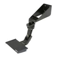
Attach the Cross Bar Mount and Linkage Assembly using M10-1.5 x 45mm Hex Head Screws.

Secure Cross Bar

Adjust and tighten the Cross Bar screw and nuts for proper frame fit.

Install Step

Mount the Step to the Linkage Assembly using M6-1.0 x 20 Socket Head Cap Screws.

Step Adjustment

Adjust the Step's height and levelness using spacers and nuts.

Product Operation

Maintenance and Care

Limited Warranty Information

Related product manuals