EasyManua.ls Logo

Bestop Trektop PRO User Manual

Bestop Trektop PRO
14 pages
To Next Page IconTo Next Page
Page #1 background imageLoading...
Page #1 background image
P1 - 54857 - Rev. A 0415
Installation Instructions - Trektop PRO Defrost Harness
© 2015 Bestop, Inc.
Installation Instructions
Trektop PRO Defrost Harness
Vehicle Application:
Bestop Trektop PRO
2007-current
Part Number 54857
Installation Tips
Before you begin installing your new Trektop PRO Defrost Harness,
please read all the instructions thoroughly.
Failure to switch off the defrost grid when the vehicle key is turned off will
cause the battery to drain.
Installation TimeTools
Skill Level
2 Hours
3 - Moderately Difficult
Drill-Driver
Qty. 14
Zip Ties
Trim
Fasteners
Trim
Removal Tool
Utility
Knife
Support
We’re here to help!
Go to www.Bestop.com and
click “Contact Us”
See a video showing
installation of this top at
www.bestop.com/video
1/4” drive
7mm Socket
1/4” Nut Driver
Safety
Glasses
1” Holesaw
POWER LOAD GROUND
Question and Answer IconNeed help?

Do you have a question about the Bestop Trektop PRO and is the answer not in the manual?

Bestop Trektop PRO Specifications

General IconGeneral
TypeSoft Top
MaterialTwill
CompatibilityJeep Wrangler JK
Side WindowsRemovable
HardwareIncluded
WarrantyLimited

Summary

Parts List

Section 1: Attach Wiring Harness to Vehicle Battery

Step 1: Battery Connections

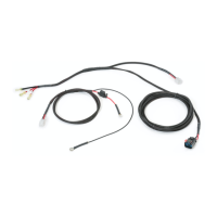
Connect the red terminal to the positive and black terminal to the negative battery posts.

Step 2: Route Harness

Route the wiring harness across the firewall and secure with zip ties.

Section 2: Pass Wiring Harness Through Vehicle Firewall

Step 1: Firewall Grommet

Push the large connector end through the firewall's rubber grommet, possibly making small cuts.

Section 3: Connect & Drill for Power Switch

Step 1: Harness Connection

Connect Harness A power connector to Harness B and zip tie Harness A.

Step 2: Drill Switch Hole

Drill a 1" hole in the dashboard trim for the power switch location.

Section 4: Install Power Switch

Step 3: Reconnect & Seat Switch

Reconnect switch to leads and snap into the 1" hole.

Section 5: Run Harness to Rear of Vehicle

Section 5: Run Harness to Rear of Vehicle (Continued)

Step 2: Connect at Rear

Bring connector out from under body lip and plug into existing vehicle harness.

Section 6: Replace Carpet and Trim Panels

Related product manuals