LaserSpeed 8000/9000 I/O Module Instruction Handbook
Installation
Part No. 93342 / Drawing No. 0921-01516 Page 11 of 84 Revision E (Dec 2013)
Connections
Connect the LaserSpeed 8000/9000 to the TO GAUGE input using the supplied
cable.
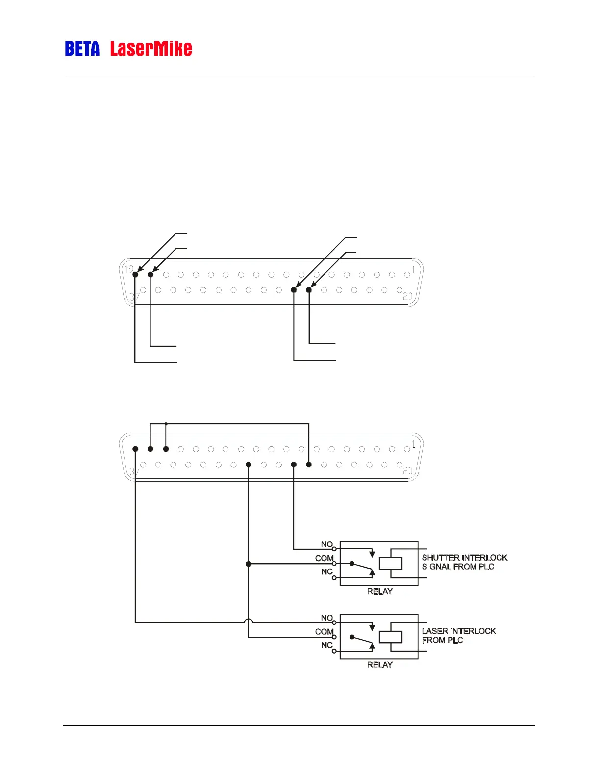
Status pins 17, 18, and 26 and 19, 27, and 30 must be connected as shown for
the gauge to operate. An interlock shunt connector is supplied with the interlock
connections pre-wired. Beta LaserMike recommends that you use the supplied
key switch to operate the Laser Interlock. This will provide you with a laser
shutoff for maintenance or material changes.
Pin 18 = Laser Interlock (+)
Pin 19 = Laser Interlock (-)
Pin 26 = Shutter Interlock (+)
Pin 27 = Shutter Interlock (-)
+5-24VDC
Ground
+5-24VDC
Ground
1819
2627
17
30
Pin 17=+5V
18=Laser+
19=Laser-
26=Shutter+
27=Shutter-
30=Ground
Pin
Pin
Pin
Pin
Pin
Note: The Setup
section of this
manual will help
you configure the
I/O Module with
the LaserSpeed
Gauge. Use the
LaserTrak
software to setup
the LaserSpeed
Gauge itself.
 Loading...