LaserSpeed 8000/9000 I/O Module Instruction Handbook
Operation
Part No. 93342 / Drawing No. 0921-01516 Page 61 of 84 Revision E (Dec 2013)
Operation
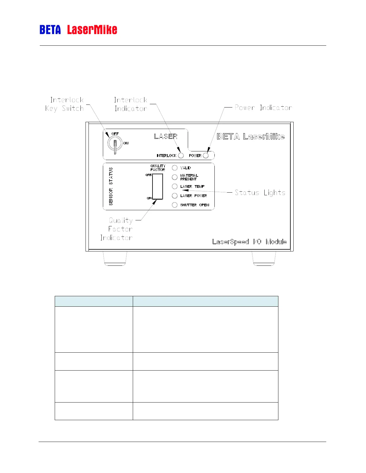
Understanding the Front Panel
The key switch is used to turn the LaserSpeed
Gauge’s laser on and off. The switch is connected in
series with the laser power jumper on the rear panel
on the connector labeled STATUS. The Key Switch
must be on, and the Interlock must be active to turn
on the Laser.
This indicator is lit when power is supplied to the
laser, indicating that the interlock is on.
This indicator shows the signal quality to the
LaserSpeed Gauge. Green indicates “Ok”, yellow in
the middle region indicates “good”, and red in the
lower region indicates a bad signal.
When lit, indicates that good measurements are
being received from the LaserSpeed.