LaserSpeed 8000/9000 I/O Module Instruction Handbook
Installation
Part No. 93342 / Drawing No. 0921-01516 Page 13 of 84 Revision E (Dec 2013)
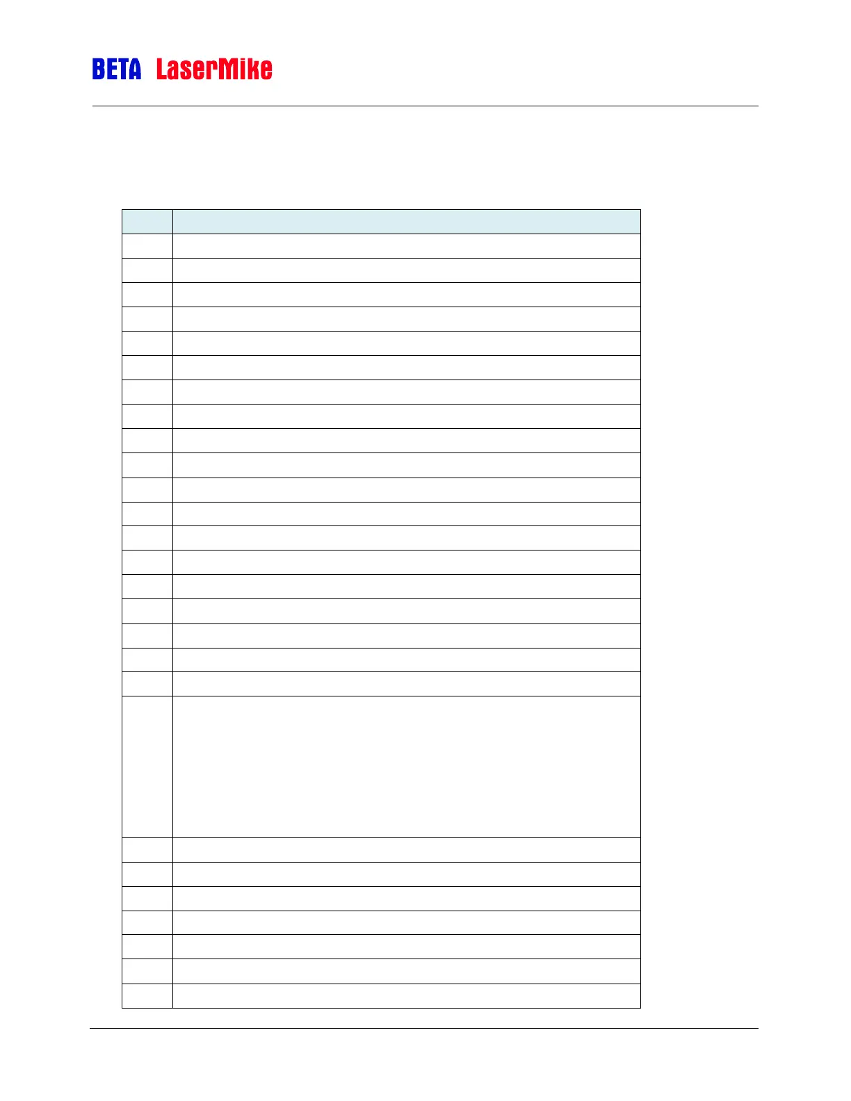
Gauge Connector Pinout
Female 37-Pin D-Subminiature
The Gauge connector is connected to the LS9000/LS8000.
RS232 Transmit (From Gauge to User)
RS232 Receive (From User to gauge)
Phase A True – High Speed output
Phase A False – User Selectable
Phase A False – High Speed Output
Phase B True – User Selectable
Phase B True – Highs Speed Output
Phase B False – User Selectable
Phase B False High Speed Output
Measurement Hold Input, can be activated by I/O Module
Signal Ground for Inputs/Outputs/Serial
Measurement Direction Input 1
Phase A True – User Selectable
Length Reset 1, can be activated by I/O Module
Signal Ground for Inputs/Outputs/Serial
User Vin: Voltage Input for Isolated Pulse Outputs (5 to 28 V DC). The
voltage supplied will be the voltage level of the pulse outputs supplied by
the LS4000-1. If a Voltage is not supplied, the pulse outputs will be TTL
level, or 3.7 volts minimum. Because this voltage input is isolated from the
power input, it must be references to one of the Signal Ground pins. For
example, if you want the pulse outputs to be 12 V outputs, use a 12 V
power supply by connecting the positive terminal to pin 20 and the ground
terminal pin to pin 11, 19, or 21.
Signal Ground for Inputs/Outputs/Serial
Index (Printer) Pulse True
Index (Printer) Pulse False
+24V Power Output (Fused)
+24V Power Output (Fused)
 Loading...