LaserSpeed 8000/9000 I/O Module Instruction Handbook
Installation
Part No. 93342 / Drawing No. 0921-01516 Page 15 of 84 Revision E (Dec 2013)
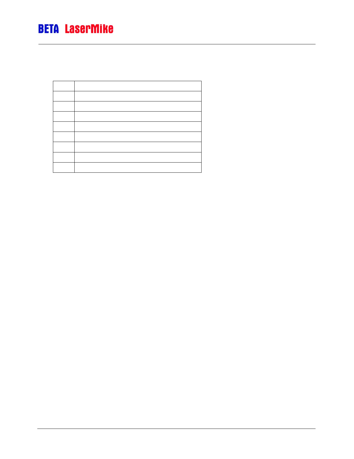
Light Stack Connector Pinout
Female 9-Pin D-Subminiature
Pulled up to 24 volts for red light stack
Pulled up to 24 volts for yellow light stack
Pulled up to 24 volts for green light stack
Reserved – Do Not Connect
Reserved – Do Not Connect
Notes:
Pin 1 (or Red on the Light Stack) is active when the Status Input from the
LS9000/LS8000 shows power is being sent to the laser and that the
Shutter is open.
Pin 2 (or Yellow on the Light Stack) is active when the Status Input from
the LS9000/LS8000 shows power is being sent to the laser and the
shutter is closed.
Pin 3 (or Green on the Light Stack) is active when there is no power
being sent to the laser.
Pin 4 and 6 are 24 volts at 1 amp for the Light Stack.
Pin 5 is signal ground.
When the red and yellow lamps flash alternately, this indicates that there are no
communications from the LaserSpeed gauge.