15 Connectivity and Information Commands
f - MU status flags (8 bits)
bit 7 VotingHW: shows voting compatibility
1 = voting compatible hardware
0 = non-voting hardware
>> There are MUs, with which voting is hardware-technically intended (MU
23 V and MU 21 V), since they have a dedicated key for it.
bit 6 CharERR: shows charging error
1 = no error
0 = error has occurred
>> A charging error can have several causes that need to be investigated
in order to make concrete statements about the source of the problem.
bit 5 CharON/OFF: shows charging status
1 = charger OFF
0 = charger ON
>> This bit indicates whether the charger is currently active and the MU is
therefore being loaded.
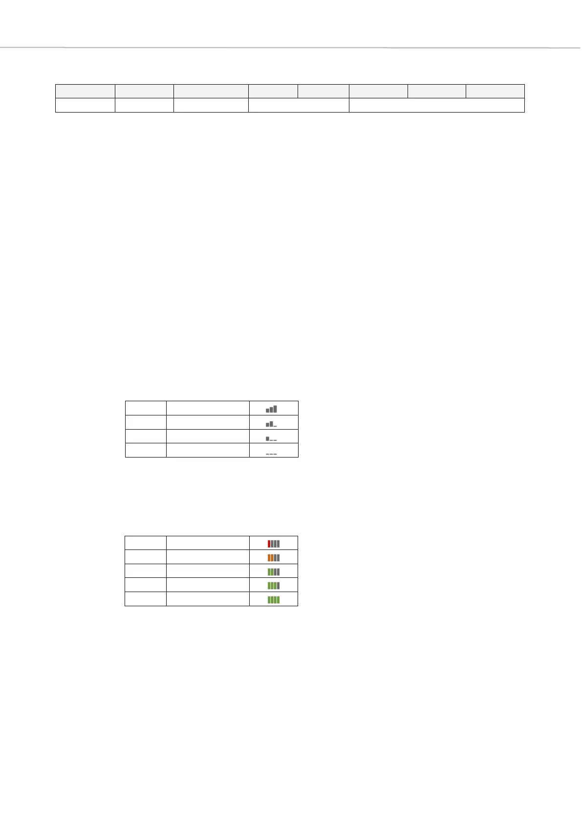
bit 4-3 RF Level: shows RF reception of each MU
>> These two bit positions represent the RF reception of the individual MUs.
As in the graphical representation in the software, a distinction is made
between four different states.
bit 2-0 BatLevel: battery level
>> The battery level is displayed in the Quinta PC software by means of a
vertical bar diagram, where no green bar stands for a state of charge
of 20% and there is an increase of 20% per bar to the maximum state of
charge of 100%.
 Loading...