BFGoodrich
Avionics Systems,
Inc.
Component
Maintenance
Manual
P/N
101-1075-()
Unregulated
Power
20 Cell Battery
Supply
32-36Vdc
Pack
250
200±20mA
10W
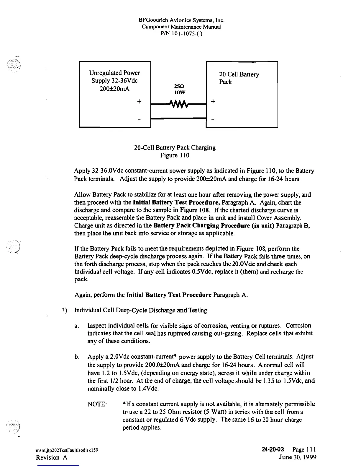
20-Cell
Battery
Pack
Charging
Figure 110
Apply
32-36.0Vde
constant-current
power
supply as indicated in
Figure l10, to the
Battery
Pack terminals. Adjust the supply
to provide
200±20mA and charge for
16-24
hours.
Allow
Battery
Pack
to
stabilize for
at
least
one hour after
removing
the power
supply,
and
then proceed with the Initial
Battery
Test
Procedure, Paragraph A.
Again,
chart the
discharge
and
compare to the sample
in Figure 108. If the charted
discharge
curve is
acceptable, reassemble the
Battery
Pack and place in unit and install Cover
Assembly.
Charge unit
as
directed in the Battery
Pack Charging Procedure
(in
unit)
Paragraph B,
then place
the
unit back into service or
storage as
applicable.
If the
Battery Pack
fails to meet the
requirements depicted
in Figure 108, perform the
Battery
Pack
deep-cycle
discharge
process again. If the Battery Pack failsthree
times,
on
the forth discharge process, stop
when
the pack reaches the 20.OVdc
and check each
individual
cell
voltage. If
any
cell
indicates
0.5Vde,
replace it (them) and
recharge
the
pack.
Again, perform
the
Initial Battery Test Procedure Paragraph A.
3) Individual Cell
Deep-Cycle
Discharge
and Testing
a. Inspect
individual cells for visible
signs
of
corrosion, venting or
ruptures. Corrosion
indicates that the cell seal has ruptured causing out-gasing. Replace cells that
exhibit
any
of these conditions.
b. Apply
a
2.0Vde
constant-current*
power supply
to the Battery Cell
terminals. Adjust
the supply to provide 200.0±20mA
and
charge for
16-24
hours. A normal
cell
will
have 1.2 to l.5Vde,
(depending on
energy state),
across it while
under
charge
within
the
first
1/2 hour. At the end
of
charge, the cell voltage should be
1.35to 1.5Vde,
and
nominally
close to
1.4Vdc.
NOTE:
*lf
a
constant current supply is not available, it is
altemately
permissible
to
use a 22 to 25 Ohm resistor (5 Watt) in series with
the
cell froma
constant or regulated
6
Vde
supply. The
same 16 to
20
hour
charge
period
applies.
msmljtp202TestFaultlsodiskl59
24-20-03
Page
111
Revision
A
June
30, 1999
 Loading...