BFGoodrich
Avionics Systems, Inc.
Component Maintenance Manual
P/N
101-1075-()
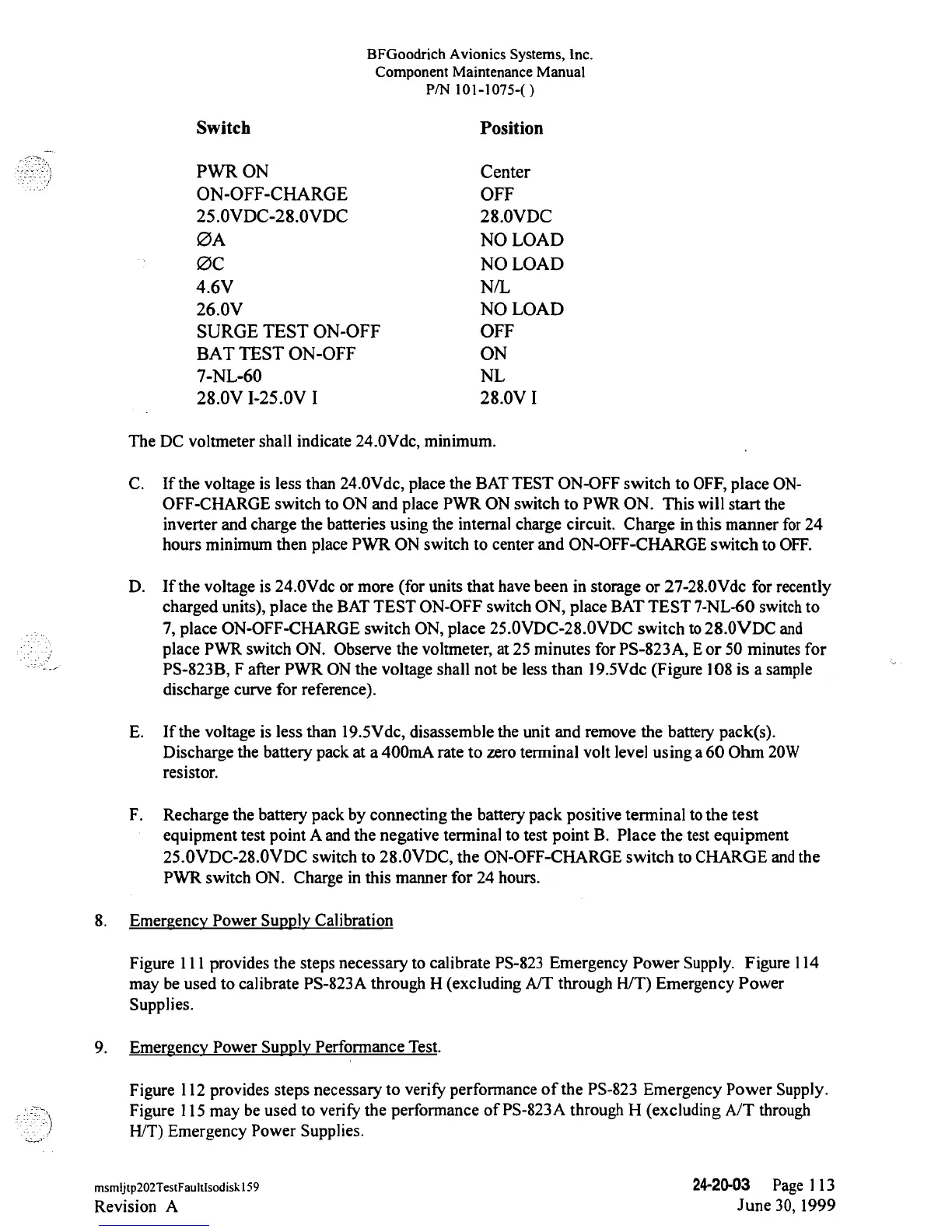
Switch
Position
PWR ON Center
ON-OFF-CHARGE
OFF
25.0VDC-28.0VDC
28.0VDC
ØA NO
LOAD
ØC
NO
LOAD
4.6V
N/L
26.0V NO LOAD
SURGE TEST
ON-OFF
OFF
BAT TEST
ON-OFF
ON
7-NL-60
NL
28.0V
I-25.0V
I 28.0V I
The
DC
voltmeter
shall indicate
24.0Vde,
minimum.
C. If the
voltage
is less than
24.0Vde,
place
the BATTEST
ON-OFF
switch
to
OFF,
place
ON-
OFF-CHARGE
switch to ON and place PWR ON
switch
to PWR ON. This will
start the
inverter and
charge
the batteries
using
the internal charge circuit.
Charge inthis manner for24
hours
minimum then place PWR
ON
switch to center and
ON-OFF-CHARGE
switch
to OFF.
D. If the
voltage is
24.0Vde or more (for units that
have
been in
storage or
27-28.0Vdc
for recently
charged units),
place the BAT
TEST
ON-OFF
switch
ON,
place BAT
TEST
7-NL-60
switch to
7,
place
ON-OFF-CHARGE
switch
ON,
place
25.0VDC-28.0VDC
switch
to 28.0VDC
and
place PWR switch
ON. Observe
the
voltmeter,
at
25 minutes for
PS-823A,
Eor 50 minutes for
PS-823B,
F
after PWR ON
the
voltage shall
not
be less than 19.5Vdc (Figure
108
is a sample
discharge curve for reference).
E. If the voltage
is
less than
19.5Vde,
disassemble the unit and remove the
battery
pack(s).
Discharge
the
battery
pack at
a 400mA rate to zero terminal
volt level
using
a 60 Ohm
20W
resistor.
F.
Recharge
the
battery
pack by
connecting
the
battery
pack positive terminal to
the
test
equipment test point A and the
negative
terminal
to
test
point
B. Place the test
equipment
25.0VDC-28.0VDC
switch to
28.0VDC,
the
ON-OFF-CHARGE
switch
to
CHARGE and the
PWR
switch
ON. Charge in this manner
for
24 hours.
8. Emergency
Power Supply Calibration
Figure 111
provides
the steps necessary to
calibrate
PS-823
Emergency
Power
Supply. Figure
114
may
be used to calibrate
PS-823A
through
H
(excluding
A/T through
H/T)
Emergency
Power
Supplies.
9.
Emergency Power Supply Performance Test.
Figure
112
provides
steps
necessary
to
verify
performance of the
PS-823
Emergency
Power
Supply.
Figure 115
may
be
used to
verify
the performance of
PS-823A
through
H
(excluding
A/T through
H/T)
Emergency
Power
Supplies.
msmijtp202TestFaultIsodiskl59
24-20-03
Page 113
Revision
A
June
30, 1999