BFGoodrich Avionics
Systems, Inc.
Component Maintenance Manual
P/N
101-1075-()
.
Corrective
Test Procedure Normal
Indication
Active
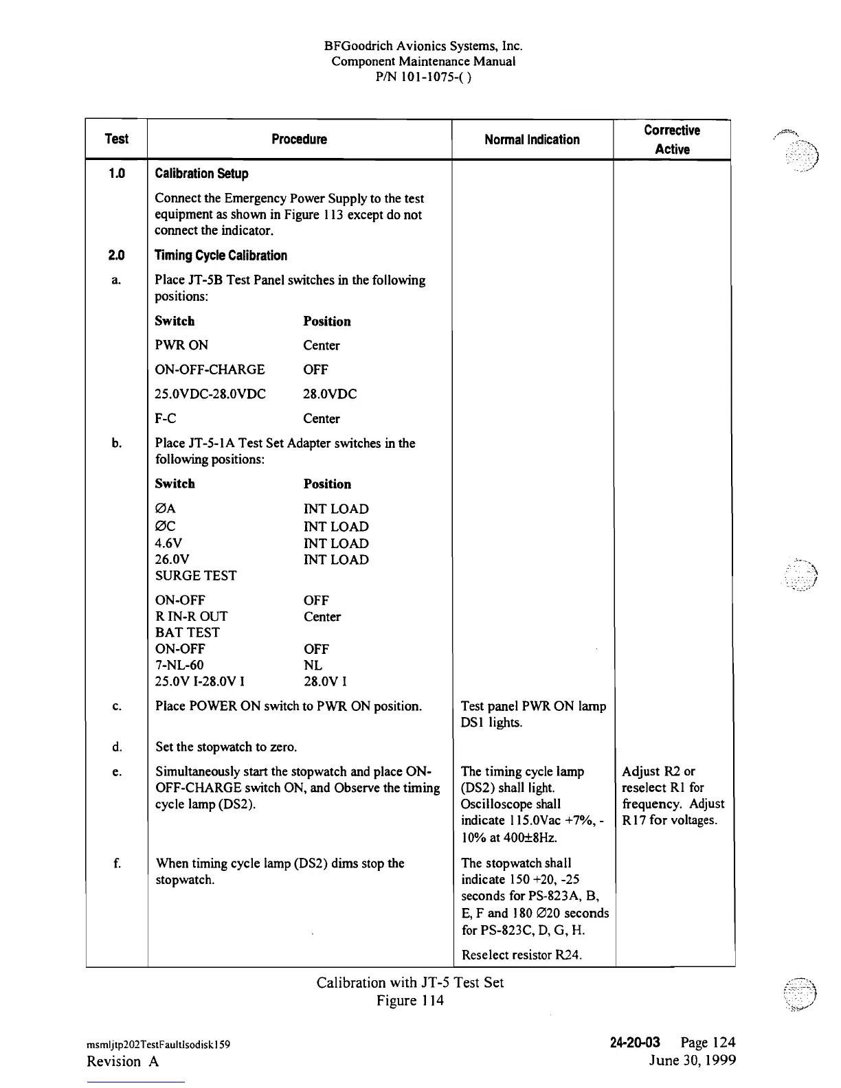
1.0
Calibration
Setup
Connect the Emergency
Power
Supply to
the test
equipment as shown in Figure l 13 except do not
connect the
indicator.
2.0
TimingCycle
Calibration
a.
Place
JT-5B
Test Panel switches
in
the
following
positions:
Switch
Position
PWR
ON Center
ON-OFF-CHARGE
OFF
25.0VDC-28.0VDC
28.0VDC
F-C
Center
b.
Place
JT-5-lA
Test Set Adapter switches
in
the
following positions:
Switch
Position
ØA
INT
LOAD
ØC
INT LOAD
4.6V
INT LOAD
26.0V
INT LOAD
SURGE TEST
ON-OFF
OFF
R
IN-R
OUT
Center
BAT TEST
ON-OFF
OFF
7-NL-60
NL
25.0V
I-28.0V
I 28.0V I
c.
Place POWER
ON
switch
to PWR ON position.
Test panel PWR ON lamp
DS1 lights.
d. Set
the stopwatch to zero.
e. Simultaneously start the stopwatch
and
place
ON-
The
timing
cycle
lamp
Adjust
R2
or
OFF-CHARGE
switch
ON, and
Observe
the timing (DS2)
shall
light.
reselect Rl for
cycle
lamp (DS2). Oscilloscope shall
frequency. Adjust
indicate 115.0Vac
+7%,
-
R17
for voltages.
10%
at 400±8Hz.
f.
When
timing
cycle lamp (DS2) dims stop
the The stopwatch shall
stopwatch.
indicate
150
+20,
-25
seconds for
PS-823A,
B,
E,
F
and
180 Ø20 seconds
for
PS-823C,
D, G,
H.
Reselect resistor R24.
Calibration
with
JT-5
Test Set
Figure
l
14
msmljtp202TestFaultlsodiskl59
24-20-03
Page
124
Revision
A
June 30, 1999