BFGoodrich
Avionics Systems,
Inc.
Component Maintenance Manual
P/N
101-1075-()
Corrective
Test Procedure NormalIndication
-
Active
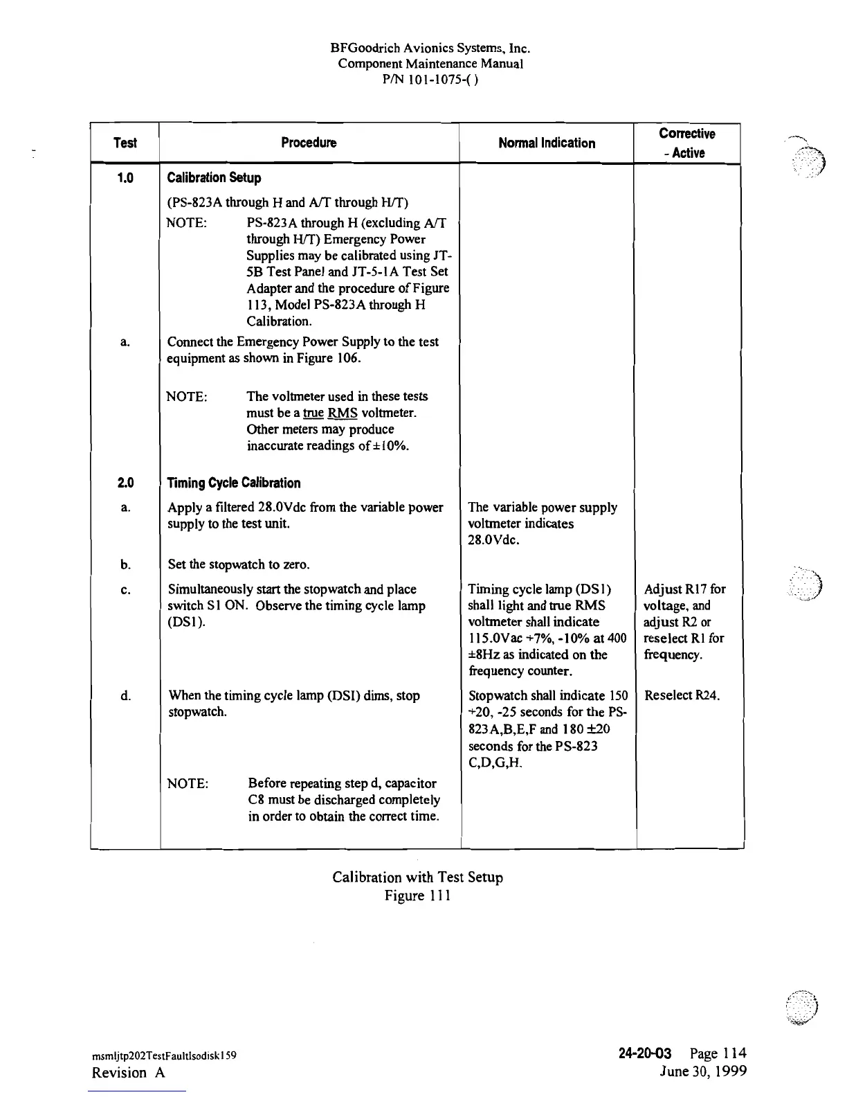
1.0
Calibration
Setup
(PS-823A
through H
and ATT
through HTT)
NOTE:
PS-823A
through H
(excluding
A/T
through HTT)
Emergency Power
Supplies may be
calibrated
using
JT-
5B Test
Panel and
JT-5-lA
Test Set
Adapter and the procedure of Figure
l
13,
Model
PS-823A
through
H
Calibration.
a.
Connect
the Emergency Power Supply
to
the test
equipment
as
shown
in
Figure 106.
NOTE:
The
voltmeter
used in
these tests
must
be a ytrue
_RMS
voltmeter.
Other
meters may
produce
inaccurate
readings
of±10%.
2.0
Timing
Cycle
Calibration
a.
Apply
a filtered 28.0Vdc
from the
variable
power
The variable
power supply
supply to
the test
unit.
voltmeter indicates
28.0Vdc.
b.
Set the stopwatch
to
zero.
c.
Simultaneously
start
the
stopwatch and
place
Timing
cycle
lamp
(DSl) Adjust RI7
for
switch SI
ON.
Observe the
timing
cycle
lamp shall light and
true
RMS voltage, and
(DSl).
voltmeter shallindicate adjust
R2
or
l l5.0Vac
+7%,
-10%
at
400
reselect Rl
for
±8Hz
as indicated on the frequency.
frequency counter.
d.
When
the
timing
cycle
lamp (DSI)
dims, stop
Stopwatch shall indicate 150 Reselect
R24.
stopwatch.
+20,
-25
seconds for the
PS-
823A,B,E,F
and 180
±20
seconds
for
the
PS-823
C,D,G,H.
NOTE: Before repeating step d, capacitor
n
omdesr
tbe dbtscWthe
dcocreme
t
Calibration with
Test
Setup
Figure
111
msmijtp202TestFaultisodisk
l
59
24-20-03
Page 1
14
Revision
A
June
30,
1999
 Loading...