BFGoodrich Avionics Systems, Inc.
Component
Maintenance Manual
P/N 101-1075-()
Corrective
Test Procedure NormalIndication
Active
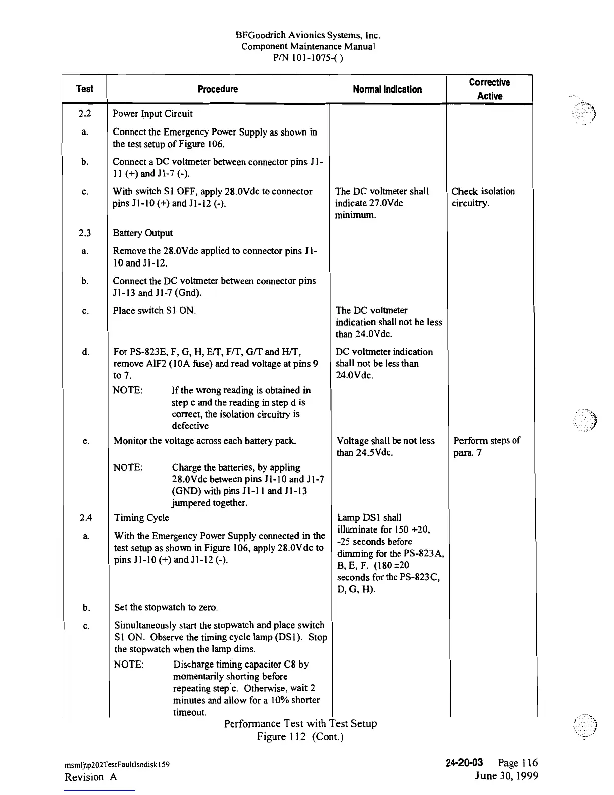
2.2 Power Input
Circuit
a. Connect the
Emergency Power
Supply as shown
in
the test
setup
of
Figure
106.
b. Connect a
DC
voltmeter
between connector pins
Jl-
ll
(+)
and
Jl
-7
(-).
c.
With switch S1 OFF,
apply 28.0Vdc to connector
The
DC
voltmeter
shall
Check
isolation
pins
Jl-l0
(+)
and
Jl-12
(-).
indicate
27.0Vdc
circuitry.
minimum.
2.3
Battery
Output
a.
Remove the
28.0Vdc
applied
to
connector pins
Jl-
10 and
Jl-l2.
b. Connect the
DC
voltmeter between connector
pins
Jl-l3
and
Jl-7
(Gnd).
c.
Place switch
Sl
ON.
The DC
voltmeter
indication
shall not
be less
than
24.0Vdc.
d.
For
PS-823E,
F,
G, H, E/T, Fif, Gif and HTT,
DC voltmeter indication
remove AlF2
(l0A
fuse) and read
voltage at
pins 9
shall
not be lessthan
to
7.
24.0Vdc.
NOTE:
If the
wrong reading is
obtained
in
step
c and
the
reading
in step d is
correct,
the isolation
circuitry
is
defective
e. Monitor the voltage across
each
battery
pack.
Voltage
shall benot
less
Perform
steps
of
than
24.5Vde.
para. 7
NOTE:
Charge the batteries,
by
appling
28.0Vdc
between
pins
Jl-l0
and
Jl-7
(GND) with pins
Jl-l
l
and
Jl-13
jumperedtogether.
2.4
Timing
Cycle
Lamp DS1
shall
. illuminate for 150+20,
a. With
the
Emergency Power
Supply connected
m the
-25
seconds before
test
setup
as
shown in
Figure
106,
apply 28.0Vdc
to
. dimming
for the
PS-823A,
pms
Jl-l0
(+)
and
Jl-l2
(-).
B, E, F. (180
±20
seconds for
the
PS-823C,
D, G, H).
b. Set the
stopwatch
to
zero.
c. Simultaneously
start
the
stopwatch
and
place switch
SI
ON.
Observe the
timing
cycle
lamp
(DSl).
Stop
the
stopwatch
when
the lamp
dims.
NOTE:
Discharge
timing
capacitor
C8
by
momentarily
shorting
before
repeating step
c.
Otherwise,
wait
2
minutes and
allow for
a 10%shorter
timeout.
Performance Test
with
"est Setup
Figure 112
(Cont.)
msmijtp202TestFaultlsodiskl59
24-20-03
Page l 16
Revision A
June
30, 1999
 Loading...