BFGoodrich Avionics Systems, Inc.
Component Maintenance Manual
P/N 101-1075-()
Corrective
Test
Procedure
Normal
Indication
Active
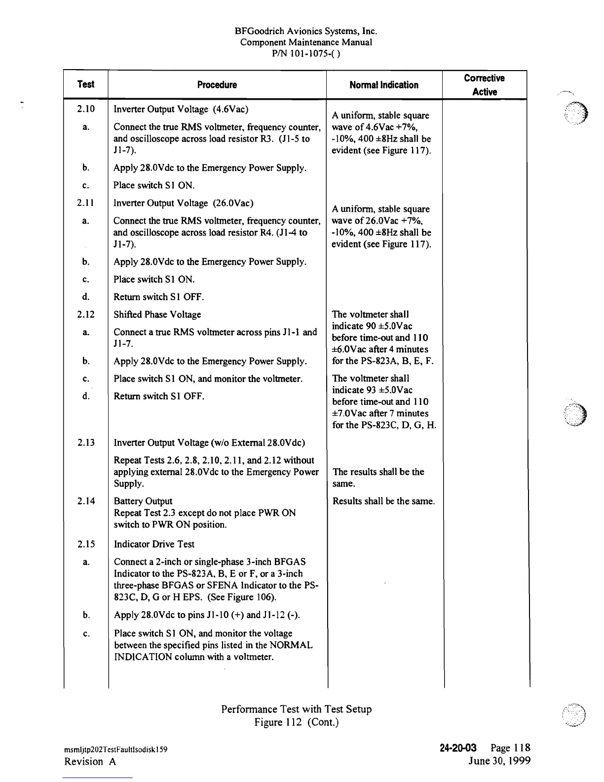
2.10
Inverter
Output Voltage
(4.6Vac)
A
uniform,
stable square
a. Connect
the
true
RMS voltmeter,
frequency
counter,
wave
of
4.6Vac
+7%,
and oscilloscope
across load
resistor
R3.
(Jl-5
to
-10%,
400
±8Hz
shall
be
Jl-7).
evident
(see
Figure
l17).
b. Apply
28.0Vdc
to the Emergency
Power
Supply.
c.
Place
switch
S1 ON.
2.11
Inverter
Output
Voltage
(26.0Vac)
A
uniform,
stable square
a.
Connect
the true RMS voltmeter,
frequency
counter,
wave
of 26.0Vac
+7%,
and
oscilloscope
across load resistor
R4.
(Jl-4
to
-10%, 400
±8Hz
shall
be
11-7).
evident
(see
Figure
117).
b. Apply
28.0Vde
to the Emergency
Power Supply.
c. Place switch
S1 ON.
d.
Return
switch
S1 OFF.
2.12
Shifted Phase Voltage
The
voltmeter shall
indicate
90
±5.0Vac
a.
Connect a true RMS voltmeter across
pins
Jl-1
and
before
time-out
and
110
Jl-7
±6.0Vac
after 4
minutes
b. Apply
28.0Vdc
to the Emergency Power Supply.
for
the
PS-823A,
B, E,
F.
c. Place switch S1
ON,
and monitor
the
voltmeter. The
voltmeter
shall
indicate 93
±5.0Vac
d. Return
switch
S1
OFF.
before
time-out
and 110
±7.0Vac
after 7 minutes
for the
PS-823C,
D, G, H.
2.13
Inverter
Output Voltage
(w/o
External
28.0Vdc)
Repeat Tests 2.6, 2.8, 2.10, 2.11, and 2.12
without
applying external 28.0Vdc to the Emergency Power The results
shall
be
the
Supply. same.
2.14
Battery Output Results shall bethe same.
Repeat
Test 2.3
except do
not
place PWR ON
switch to
PWR
ON
position.
2.15
Indicator
Drive
Test
a.
Connect a
2-inch
or
single-phase 3-inch
BFGAS
Indicator
to the
PS-823A,
B, E
or
F, or a
3-inch
three-phase
BFGAS
or SFENA lndicator
to
the
PS-
823C,
D, G
or
H EPS. (See
Figure
106).
b.
Apply
28.0Vdc
to pins
Jl-10
(+)
and
Jl-12
(-).
c.
Place switch
S1 ON, and monitor
the
voltage
between the specified pins listed in the
NORMAL
INDICATION column
with
a
voltmeter.
Performance Test
with Test Setup
Figure 112 (Cont.)
msmljtp202TestFaultIsodisklS9
24-20-03
Page
118
Revision
A
June 30, 1999
 Loading...