BFGoodrich Avionics Systems, Inc.
Component Maintenance Manual
P/N
101-1075-()
Corrective
Test Procedure
NormalIndication
Active
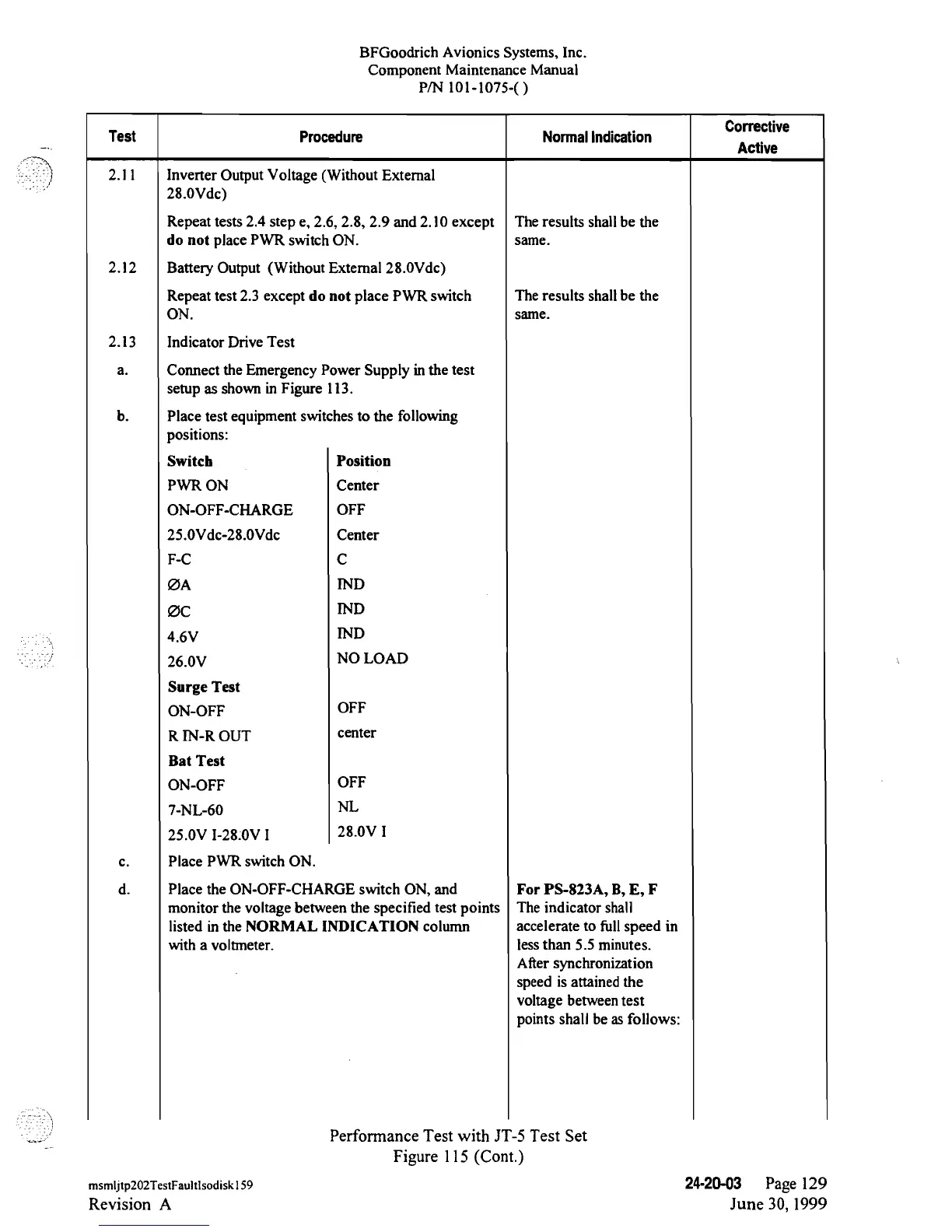
2.11 Inverter Output
Voltage
(Without
Extemal
28.0Vdc)
Repeat tests
2.4
step e,
2.6,
2.8, 2.9 and
2.10
except
The results shall be the
do not place PWR switch ON.
same.
2.12
Batterj Output
(Without
Extemal
28.0Vdc)
Repeat
test 2.3 except do
not place PWR
switch The results shall be the
ON.
same.
2.13
Indicator
Drive Test
a.
Connect
the Emergency Power
Supply in
the test
setup
as
shown in Figure
113.
b. Place test
equipment switches to the following
positions:
Switch
Position
PWR
ON
Center
ON-OFF-CHARGE
OFF
25.0Vdc-28.0Vdc
Center
F-C
C
ØA
IND
ØC
IND
4.6V
IND
26.0V
NO
LOAD
Surge Test
ON-OFF
OFF
R
IN-R
OUT
center
Bat Test
ON-OFF
OFF
7-NL-60
NL
25.0V
I-28.0V
I
28.0V
I
c. Place
PWR switch
ON.
d. Place the
ON-OFF-CHARGE
switch
ON,
and
For
PS-823A,
B, E,
F
monitor the voltage
between the specified
test
points The indicator
shall
listed
in
the NORMAL
INDICATION column accelerate to
full
speed
in
with
a voltmeter.
lessthan 5.5 minutes.
After
synchronization
speed is attained
the
voltage
betweentest
points
shall be as follows:
Performance Test with
JT-5
Test Set
Figure 115 (Cont.)
msmljtp202TestFaultlsodiskl59
24-20-03
Page 129
Revision
A
June
30,
1999
 Loading...